PINNED - Roboteq Controller - developing for powerchairs
Re: PINNED - Roboteq Controller - developing for powerchairs
![]() by snaker » 18 Apr 2023, 03:11
by snaker » 18 Apr 2023, 03:11
-

snaker - Posts: 1195
- Joined: 23 May 2015, 10:45
- Location: Vietnam
Re: PINNED - Roboteq Controller - developing for powerchairs
![]() by JMGarage » 18 Apr 2023, 04:52
by JMGarage » 18 Apr 2023, 04:52
First pic is for DOUT.
Then there is STO feature on newer controllers for emergency stop. It should be safe way stop all. Older controller doesn't have this.
I found CANBed V1 what I am going to use.
https://www.longan-labs.cc/1030008.html
- JMGarage
- Posts: 8
- Joined: 11 Aug 2022, 05:30
Re: PINNED - Roboteq Controller - developing for powerchairs
![]() by Burgerman » 18 Apr 2023, 08:17
by Burgerman » 18 Apr 2023, 08:17
-

Burgerman - Site Admin
- Posts: 65281
- Joined: 27 May 2008, 21:24
- Location: United Kingdom
Re: PINNED - Roboteq Controller - developing for powerchairs
![]() by JMGarage » 18 Apr 2023, 08:25
by JMGarage » 18 Apr 2023, 08:25
- JMGarage
- Posts: 8
- Joined: 11 Aug 2022, 05:30
Re: PINNED - Roboteq Controller - developing for powerchairs
![]() by Burgerman » 18 Apr 2023, 08:46
by Burgerman » 18 Apr 2023, 08:46
But no need.
Ebay TVS diodes, use on all inputs and outputs on the robiteq to clip spikes from damaging the inputs. Choose the voltage above your working voltage and below the roboteqs max input voltage limit.
For the diodes across the fuse, and across the contactor use any solar type diode 30A or so is enough as it is just a short term safety so they can cope.
Wiring as per roboteq manual.
I also used 2 SSRs - dc to dc, so that the roboteq doesent see the spikes from the contactor, or the chairs brakes, directly and only has to drive the SSRs. Low load/current.
-
Burgerman - Site Admin
- Posts: 65281
- Joined: 27 May 2008, 21:24
- Location: United Kingdom
Re: PINNED - Roboteq Controller - developing for powerchairs
![]() by snaker » 18 Apr 2023, 08:47
by snaker » 18 Apr 2023, 08:47
The latching relay already embeds 2 diodes inside (one for setting, one for resetting). So I can bypass the diode for the contactor safety pin (DOUT).
For the diode in series with the precharge resistor. What type of diode should I use? What's its amps rating, voltage?
-
snaker - Posts: 1195
- Joined: 23 May 2015, 10:45
- Location: Vietnam
Re: PINNED - Roboteq Controller - developing for powerchairs
![]() by Burgerman » 18 Apr 2023, 08:54
by Burgerman » 18 Apr 2023, 08:54
-
Burgerman - Site Admin
- Posts: 65281
- Joined: 27 May 2008, 21:24
- Location: United Kingdom
Re: PINNED - Roboteq Controller - developing for powerchairs
![]() by snaker » 18 Apr 2023, 09:11
by snaker » 18 Apr 2023, 09:11
 But I am afraid that the stud will cause difficulty when soldering it to a cable. I found this diode 20A10 (20A, 1000V). Is it Ok?
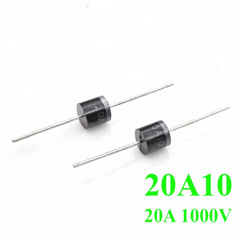
-
snaker - Posts: 1195
- Joined: 23 May 2015, 10:45
- Location: Vietnam
Re: PINNED - Roboteq Controller - developing for powerchairs
![]() by Burgerman » 18 Apr 2023, 19:53
by Burgerman » 18 Apr 2023, 19:53
-
Burgerman - Site Admin
- Posts: 65281
- Joined: 27 May 2008, 21:24
- Location: United Kingdom
 Re: PINNED - Roboteq Controller - developing for powerchairs
![]() by LROBBINS » 18 Apr 2023, 22:29
by LROBBINS » 18 Apr 2023, 22:29
The Roboteq Dout pins can handle a maximum of 1 Amp (and no more than 4.5 Amps for all Dout combined). I don't have its data sheet handy, but my recollection is that the latching relay John used draws much more than 1 Amp - hence using solid state relays between the Dout and a latching relay as he does is ESSENTIAL. Overloading a Dout will destroy at least that gate, and may even destroy the whole Dout chip. If just one gate goes bad, you can switch to using a different one, but if the chip is destroyed so is the Roboteq (unless you pay dearly to have it repaired).
Non-latching relays draw much less current; the one I'm using draws 0.17 Amps so can be powered directly from a Dout, but, of course, it is on the whole time the motors are powered. To improve its service life, the script has a CONTACTOR subroutine that opens and closes Dout for the contactor only when negligible current is flowing: a few msec before sending power to motors, or when motor output has fallen to near 0. This means that in normal operation the relay coil is not active all the time, but only when the motors are running and by doing the switching when little or no current is flowing means that there's no contact arcing to damage the relay itself. (This way of doing things was vetted for me by TE application engineering.)
Having the relay Dout switch on and off, however, means it can't be directly used for Roboteq's fault detection, so I also added a CK_RUNAWAY subroutine that actually does two things. One is that it reads the MOSFET fail flag in the Roboteq firmware and uses that to open the contactor Dout. The other is that it will detect a runaway condition and open the contactor in that situation as well; a runaway state is defined as anytime that motor command and motor power are ZERO but there's even minimal current flowing for 500 msec. These two subroutines essentially mimic Roboteq's fault detection, but still allow the CONTACTOR subroutine to work the relay without contact arcing, and not have its coil powered even when not moving.
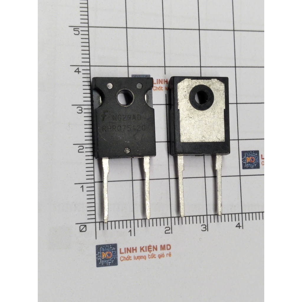
The stud of a stud mount diode doesn't get directly soldered. Solder a ring terminal in your wiring harness and then use a nut to secure that to the diode.
Paralleling two diodes may not get you double the current rating. No two diodes will be exactly matched and the forward voltage drop can be substantially different for the two in at least some conditions - especially as they are warmed by current flowing through them. The result is that
one will pass more current than the other and may fail at not much more that the rated current of just one diode. What can happen is that first one diode fails, then all the current goes through the other one, and it fails too. Its better to use a single large capacity diode for the contactor's (reverse voltage) bypass.
- LROBBINS
- Posts: 5553
- Joined: 27 Aug 2010, 09:36
- Location: Siena, Italy
Re: PINNED - Roboteq Controller - developing for powerchairs
![]() by Vitolds » 18 Apr 2023, 23:09
by Vitolds » 18 Apr 2023, 23:09
I also made a controller board with a mini relay. when the 12V power is turned off, the relay always turns off the controller.
- Attachments
-
-
- Vitolds
- Posts: 531
- Joined: 26 Mar 2014, 22:12
- Location: Moscow Russia
Re: PINNED - Roboteq Controller - developing for powerchairs
![]() by snaker » 19 Apr 2023, 01:57
by snaker » 19 Apr 2023, 01:57
-
snaker - Posts: 1195
- Joined: 23 May 2015, 10:45
- Location: Vietnam
Re: PINNED - Roboteq Controller - developing for powerchairs
![]() by snaker » 21 Apr 2023, 10:36
by snaker » 21 Apr 2023, 10:36
- Attachments
-
- diagram.png (10.68 KiB) Viewed 1998 times
-
snaker - Posts: 1195
- Joined: 23 May 2015, 10:45
- Location: Vietnam
Re: PINNED - Roboteq Controller - developing for powerchairs
![]() by Burgerman » 21 Apr 2023, 10:59
by Burgerman » 21 Apr 2023, 10:59
And at 48V and roboteq at 0v with 500Ohm you will get this:
Current (I) = 0.096 Amps
Power (P) = 4.608 watts
Peak. Dropping further and fast over time. So no problem.
-
Burgerman - Site Admin
- Posts: 65281
- Joined: 27 May 2008, 21:24
- Location: United Kingdom
Re: PINNED - Roboteq Controller - developing for powerchairs
![]() by snaker » 22 Apr 2023, 02:12
by snaker » 22 Apr 2023, 02:12
- diagram.png (10.98 KiB) Viewed 1983 times
I also ordered 3 Fotek relays (for the emergency relay, brakes and lights).
-
snaker - Posts: 1195
- Joined: 23 May 2015, 10:45
- Location: Vietnam
Re: PINNED - Roboteq Controller - developing for powerchairs
![]() by Burgerman » 22 Apr 2023, 03:02
by Burgerman » 22 Apr 2023, 03:02
-
Burgerman - Site Admin
- Posts: 65281
- Joined: 27 May 2008, 21:24
- Location: United Kingdom
Re: PINNED - Roboteq Controller - developing for powerchairs
![]() by snaker » 22 Apr 2023, 04:01
by snaker » 22 Apr 2023, 04:01
14s pack, max voltage = 14x3.600V = 50.4V => 51V TVS diode?
16s pack, max voltage = 16x3.600V = 57.6V => 58V TVS diode?
- Attachments
-
-
snaker - Posts: 1195
- Joined: 23 May 2015, 10:45
- Location: Vietnam
Re: PINNED - Roboteq Controller - developing for powerchairs
![]() by Burgerman » 22 Apr 2023, 05:24
by Burgerman » 22 Apr 2023, 05:24
-
Burgerman - Site Admin
- Posts: 65281
- Joined: 27 May 2008, 21:24
- Location: United Kingdom
Re: PINNED - Roboteq Controller - developing for powerchairs
![]() by Burgerman » 22 Apr 2023, 05:35
by Burgerman » 22 Apr 2023, 05:35
-
Burgerman - Site Admin
- Posts: 65281
- Joined: 27 May 2008, 21:24
- Location: United Kingdom
Re: PINNED - Roboteq Controller - developing for powerchairs
![]() by snaker » 22 Apr 2023, 10:40
by snaker » 22 Apr 2023, 10:40
- Attachments
-
-
snaker - Posts: 1195
- Joined: 23 May 2015, 10:45
- Location: Vietnam
Re: PINNED - Roboteq Controller - developing for powerchairs
![]() by Burgerman » 22 Apr 2023, 11:53
by Burgerman » 22 Apr 2023, 11:53
I think I used the 5v on the roboteq to drive the ssrs, and the 12v fed the other side of the SSR. And then to brake, contactor etc. This stuff all gave me a headache at the time! At leasy your diode is the right way around. I aturally fitted mine pos end to the battery. Then it came to me while in the pub that when power was cut the robeteq fed the battery!

You need to think of every eventuality.
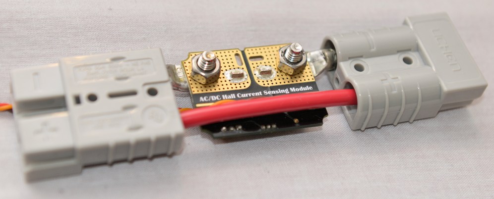
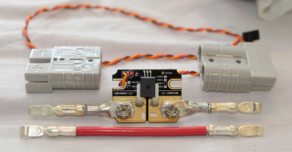
Have you made up any current sensors for the motors? It can be done without. But its not as precise. I use them.
https://www.wheelchairdriver.com/BM3-co ... -parts.jpg
https://www.wheelchairdriver.com/BM3-co ... r-rear.jpg
https://www.wheelchairdriver.com/BM3-co ... rimped.jpg
https://www.wheelchairdriver.com/BM3-co ... shrink.jpg
Or your RC setup?
Or your joystick? It needs RC on off latched switch, speed pot, inc end resistors, status LED, RC ON LED, roboteq on/off, contactor on/off. Etc.
https://www.wheelchairdriver.com/BM3-co ... -small.jpg
-
Burgerman - Site Admin
- Posts: 65281
- Joined: 27 May 2008, 21:24
- Location: United Kingdom
Re: PINNED - Roboteq Controller - developing for powerchairs
![]() by JMGarage » 22 Apr 2023, 12:09
by JMGarage » 22 Apr 2023, 12:09
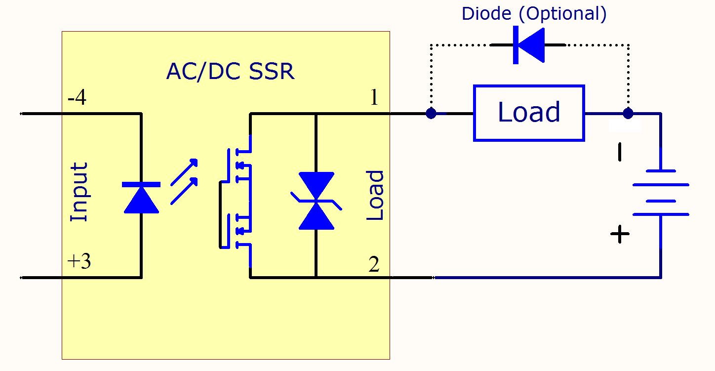
Load side You can add that diode. Input side don't need SSR.
https://electricala2z.com/wp-content/up ... C_Load.png
- JMGarage
- Posts: 8
- Joined: 11 Aug 2022, 05:30
Re: PINNED - Roboteq Controller - developing for powerchairs
![]() by Burgerman » 22 Apr 2023, 12:13
by Burgerman » 22 Apr 2023, 12:13
-
Burgerman - Site Admin
- Posts: 65281
- Joined: 27 May 2008, 21:24
- Location: United Kingdom
Re: PINNED - Roboteq Controller - developing for powerchairs
![]() by snaker » 24 Apr 2023, 10:12
by snaker » 24 Apr 2023, 10:12
I am still at the initial steps. There is a long way in front.
I must test the project without current sensors first. I will not use RC. I will use an used VR2 joystick first for testing. I might upgrade APEM joystick later if everything is tested Ok and works. But those final steps are in a far future
- Attachments
-
-
snaker - Posts: 1195
- Joined: 23 May 2015, 10:45
- Location: Vietnam
Re: PINNED - Roboteq Controller - developing for powerchairs
![]() by Burgerman » 24 Apr 2023, 10:33
by Burgerman » 24 Apr 2023, 10:33
The LARGE one way diode goes across the contactor along with the precharge resistor.
And the contactor will also need a switch on and off (momentary switches at 12V) on the joystick.
-
Burgerman - Site Admin
- Posts: 65281
- Joined: 27 May 2008, 21:24
- Location: United Kingdom
Re: PINNED - Roboteq Controller - developing for powerchairs
![]() by Burgerman » 24 Apr 2023, 10:42
by Burgerman » 24 Apr 2023, 10:42
I will not use RC.
Trust me it makes setting everything up, and figuring everything out 100x easier. And safe. And its also useful afterwards. You certainly will never regret it.
-
Burgerman - Site Admin
- Posts: 65281
- Joined: 27 May 2008, 21:24
- Location: United Kingdom
Re: PINNED - Roboteq Controller - developing for powerchairs
![]() by snaker » 25 Apr 2023, 09:11
by snaker » 25 Apr 2023, 09:11
BM, do you remember the value of the resistor in the diagram?
- Attachments
-
-
snaker - Posts: 1195
- Joined: 23 May 2015, 10:45
- Location: Vietnam
Re: PINNED - Roboteq Controller - developing for powerchairs
![]() by JMGarage » 25 Apr 2023, 09:51
by JMGarage » 25 Apr 2023, 09:51
- JMGarage
- Posts: 8
- Joined: 11 Aug 2022, 05:30
Re: PINNED - Roboteq Controller - developing for powerchairs
![]() by snaker » 25 Apr 2023, 10:08
by snaker » 25 Apr 2023, 10:08
- Attachments
-
-
snaker - Posts: 1195
- Joined: 23 May 2015, 10:45
- Location: Vietnam
Re: PINNED - Roboteq Controller - developing for powerchairs
![]() by JMGarage » 25 Apr 2023, 10:17
by JMGarage » 25 Apr 2023, 10:17
- JMGarage
- Posts: 8
- Joined: 11 Aug 2022, 05:30
Return to Everything Powerchair
Who is online
Users browsing this forum: AgGuy and 54 guests