DWIZ-ADAPT
Re: DWIZ-ADAPT
![]() by LROBBINS » 18 Feb 2016, 19:27
by LROBBINS » 18 Feb 2016, 19:27
- LROBBINS
- Posts: 5553
- Joined: 27 Aug 2010, 09:36
- Location: Siena, Italy
Re: DWIZ-ADAPT
![]() by anubis801 » 18 Feb 2016, 20:55
by anubis801 » 18 Feb 2016, 20:55
Without the security dongle to unlock/license the "original" Wizard software program, you can only read the status report from your controller with this circuit.
In theory the dongle is just a license key which the software looks for through a software hardware driver.
Well, that is if you want to keep it legal
Not really a problem for Russia and China
- anubis801
- Posts: 15
- Joined: 25 Mar 2015, 00:05
Re: DWIZ-ADAPT
![]() by anubis801 » 09 Mar 2016, 16:17
by anubis801 » 09 Mar 2016, 16:17
I got 10 PCB's left over, if anyone is interested in a bare PCB send me a PM.
- Attachments
-
- Programmer
- anubis801
- Posts: 15
- Joined: 25 Mar 2015, 00:05
Re: DWIZ-ADAPT
![]() by woodygb » 22 Mar 2016, 12:58
by woodygb » 22 Mar 2016, 12:58
e.g. http://www.ebay.co.uk/itm/NEW-USB2-0-TO ... SwuAVWx9ih
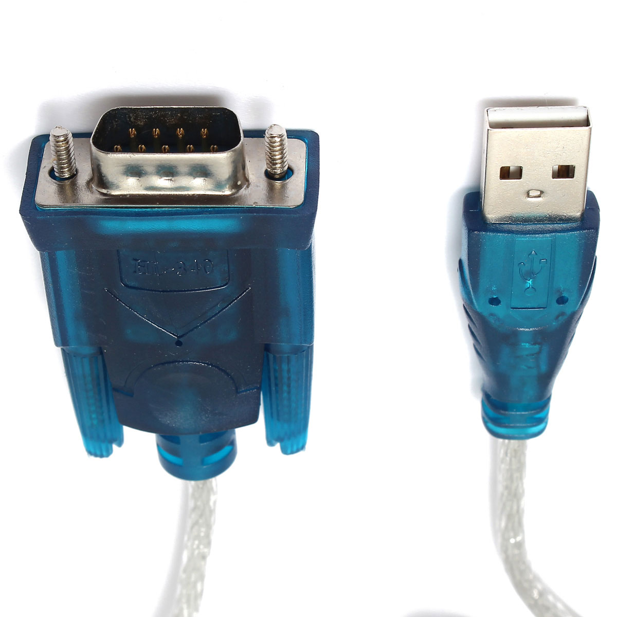
This adapter MUST use a win chip head CH340/341 or HL340 NOT a Prolific chip.
You will see 340 embossed on the RS232 end of the cable.
Wizard snapshot.
Niels Bohr
-

woodygb - Posts: 7070
- Joined: 12 Mar 2011, 18:45
- Location: Bedford UK
Re: DWIZ-ADAPT
![]() by woodygb » 22 Mar 2016, 15:34
by woodygb » 22 Mar 2016, 15:34
I'll probably ask you to test two options on the wheelchair version...one will be using your DWIZ-ADAPT and the above Rhino solution...the other a guess at what the signal mode is that is coming via the charging port and without the DWIZ-ADAPT.
Niels Bohr
-
woodygb - Posts: 7070
- Joined: 12 Mar 2011, 18:45
- Location: Bedford UK
Re: DWIZ-ADAPT
![]() by terry2 » 22 Mar 2016, 15:36
by terry2 » 22 Mar 2016, 15:36
woodygb wrote:NOTE:- The Rhino scooter controller.... unlike wheelchair controllers/joysticks ....doesn't need the DWIZ-ADAPT as it has one built in to it.
I'll probably ask you to test two options on the wheelchair version.
I'm all for testing
Was your OS win 98 or win 7?
-

terry2 - Posts: 1281
- Joined: 07 Nov 2014, 12:08
- Location: Solihull
Re: DWIZ-ADAPT
![]() by woodygb » 22 Mar 2016, 15:40
by woodygb » 22 Mar 2016, 15:40
Niels Bohr
-
woodygb - Posts: 7070
- Joined: 12 Mar 2011, 18:45
- Location: Bedford UK
Re: DWIZ-ADAPT
![]() by LROBBINS » 22 Mar 2016, 17:04
by LROBBINS » 22 Mar 2016, 17:04
Ciao,
Lenny
- LROBBINS
- Posts: 5553
- Joined: 27 Aug 2010, 09:36
- Location: Siena, Italy
Re: DWIZ-ADAPT
![]() by woodygb » 22 Mar 2016, 17:14
by woodygb » 22 Mar 2016, 17:14
BTW ..Terry has a DWIZ-ADAPT ....which he has currently lent me ...perhaps in a week or 2 we can find a simple solution to the DWIZ-ADAPT.
P.S. Does anyone know the EXACT designation of the Hirose plug/socket?
Niels Bohr
-
woodygb - Posts: 7070
- Joined: 12 Mar 2011, 18:45
- Location: Bedford UK
Re: DWIZ-ADAPT
![]() by LROBBINS » 22 Mar 2016, 17:18
by LROBBINS » 22 Mar 2016, 17:18
- LROBBINS
- Posts: 5553
- Joined: 27 Aug 2010, 09:36
- Location: Siena, Italy
Re: DWIZ-ADAPT
![]() by terry2 » 31 Mar 2016, 15:51
by terry2 » 31 Mar 2016, 15:51
Nice one woody.
I see my speed is set too 90%! will I have more SPEED if I crank it to 100%
-
terry2 - Posts: 1281
- Joined: 07 Nov 2014, 12:08
- Location: Solihull
Re: DWIZ-ADAPT
![]() by rover220 » 31 Mar 2016, 17:07
by rover220 » 31 Mar 2016, 17:07
terry2 wrote:The cable with the dwiz is working on my Puma 40
Nice one woody.
I see my speed is set too 90%! will I have more SPEED if I crank it to 100%
Do you have a hasp key to enable you to make any changes?
- rover220
- Posts: 1846
- Joined: 10 Dec 2013, 19:34
- Location: West Mids, UK
Re: DWIZ-ADAPT
![]() by terry2 » 31 Mar 2016, 17:08
by terry2 » 31 Mar 2016, 17:08
Burgerman wrote:Why bother with 90?
That was my thinking. I don't think 10% will make much difference. My batteries will be install tomoz.
So I will see after charging.
I also noticed there are 5 profiles to play with. My chair only shows 4?
-
terry2 - Posts: 1281
- Joined: 07 Nov 2014, 12:08
- Location: Solihull
Re: DWIZ-ADAPT
![]() by rover220 » 31 Mar 2016, 17:15
by rover220 » 31 Mar 2016, 17:15
terry2 wrote:Burgerman wrote:Why bother with 90?
That was my thinking. I don't think 10% will make much difference. My batteries will be install tomoz.
So I will see after charging.
I also noticed there are 5 profiles to play with. My chair only shows 4?
Look in the joystick options and you'll see the max number of drive profiles. Change that to 5 and you'll have 5 available.
- rover220
- Posts: 1846
- Joined: 10 Dec 2013, 19:34
- Location: West Mids, UK
Re: DWIZ-ADAPT
![]() by terry2 » 31 Mar 2016, 17:16
by terry2 » 31 Mar 2016, 17:16
rover220 wrote:terry2 wrote:Burgerman wrote:Why bother with 90?
That was my thinking. I don't think 10% will make much difference. My batteries will be install tomoz.
So I will see after charging.
I also noticed there are 5 profiles to play with. My chair only shows 4?
Look in the joystick options and you'll see the max number of drive profiles. Change that to 5 and you'll have 5 available.
Nice bit of info there. Thank you so much
I'll try and find a manual on it be for messing
-
terry2 - Posts: 1281
- Joined: 07 Nov 2014, 12:08
- Location: Solihull
Re: DWIZ-ADAPT
![]() by terry2 » 31 Mar 2016, 17:27
by terry2 » 31 Mar 2016, 17:27
rover220 wrote:Do you have the hasp key/dongle?
No woody done his wizardry on my dwiz and a serial cable.
-
terry2 - Posts: 1281
- Joined: 07 Nov 2014, 12:08
- Location: Solihull
Re: DWIZ-ADAPT
![]() by Burgerman » 31 Mar 2016, 17:42
by Burgerman » 31 Mar 2016, 17:42
-

Burgerman - Site Admin
- Posts: 65233
- Joined: 27 May 2008, 21:24
- Location: United Kingdom
Re: DWIZ-ADAPT
![]() by woodygb » 31 Mar 2016, 21:11
by woodygb » 31 Mar 2016, 21:11
rover220 wrote:Do you have the hasp key/dongle?
Dongle less program.
Niels Bohr
-
woodygb - Posts: 7070
- Joined: 12 Mar 2011, 18:45
- Location: Bedford UK
Re: DWIZ-ADAPT
![]() by DAIWTHOMAS » 10 Apr 2016, 08:15
by DAIWTHOMAS » 10 Apr 2016, 08:15
- DAIWTHOMAS
- Posts: 2
- Joined: 08 Apr 2016, 20:26
Re: DWIZ-ADAPT
![]() by gcebiker » 19 Apr 2016, 12:51
by gcebiker » 19 Apr 2016, 12:51
anubis801 wrote:Finished!
I got 10 PCB's left over, if anyone is interested in a bare PCB send me a PM.
Anubis PMing you, tho i have the factory dongle its always good to have a spare.
My YouTube Ch -- https://www.youtube.com/user/gcebiker
-

gcebiker - Posts: 879
- Joined: 11 Jul 2015, 14:20
- Location: Gold Coast, Queensland, Australia.
Re: DWIZ-ADAPT
![]() by woodygb » 19 Apr 2016, 12:56
by woodygb » 19 Apr 2016, 12:56
viewtopic.php?f=2&t=4095&start=20#p78602
Niels Bohr
-
woodygb - Posts: 7070
- Joined: 12 Mar 2011, 18:45
- Location: Bedford UK
Re: DWIZ-ADAPT
![]() by gcebiker » 19 Apr 2016, 13:26
by gcebiker » 19 Apr 2016, 13:26
It will be good to offer them an alternative, i am limited in my ability to travel to their home and them to travel to mine with the big power chair.
This device is a god send.
My YouTube Ch -- https://www.youtube.com/user/gcebiker
-
gcebiker - Posts: 879
- Joined: 11 Jul 2015, 14:20
- Location: Gold Coast, Queensland, Australia.
Re: DWIZ-ADAPT
![]() by woodygb » 19 Apr 2016, 13:42
by woodygb » 19 Apr 2016, 13:42
Niels Bohr
-
woodygb - Posts: 7070
- Joined: 12 Mar 2011, 18:45
- Location: Bedford UK
Re: DWIZ-ADAPT
![]() by woodygb » 19 Apr 2016, 14:00
by woodygb » 19 Apr 2016, 14:00
...Meaning the data pin of the controller.The voltage output at the signal pin is 9.8v according to my meter ... this is a Serial level voltage not TTL.
Niels Bohr
-
woodygb - Posts: 7070
- Joined: 12 Mar 2011, 18:45
- Location: Bedford UK
Re: DWIZ-ADAPT
![]() by anubis801 » 19 Apr 2016, 15:11
by anubis801 » 19 Apr 2016, 15:11
woodygb wrote:The voltage output at the signal pin is 9.8v according to my meter ... this is a Serial level voltage not TTL.
It may look like a RS-232 serial but it's not RS-232 standard.
It is Serial comunication alright but neither RS-232 nor TTL logic levels!
It's more like TTL-serial with CMOS voltage levels.
Logic level 0 = 1-2V / logic 1 level = 10V while the RS-232 levels are Logic 0 = 9 to 12V and Logic 1 = -9 to -12V (negative voltage)
- anubis801
- Posts: 15
- Joined: 25 Mar 2015, 00:05
Re: DWIZ-ADAPT
![]() by gcebiker » 20 Apr 2016, 08:48
by gcebiker » 20 Apr 2016, 08:48
Arduino TX to the Middle pin, Ground to Ground on the Arduino.
- Code: Select all
void setup() {
  Serial.begin(9600);
  delay(300);
}

void loop() {
  {
    Serial.write(248);
    Serial.write(134);

  delay(11);


    Serial.write(254);
    Serial.write(248);
    Serial.write(230);
    Serial.write(128);
    Serial.write(152);
    Serial.write(128);
  }
delay(229);
}
Writing that code to the middle pin
- Base was responding that a Hand Held Programmer was connected (Saleae Logic Analyzer data capture on RS485 data lines).
- Led strobe was on also indicating Programmer connected
Excerpt from the manual - note that here they are talking specifically about the Data line between the Joystick and power base but it also is seen to hold true for the Pin 3 which it would seem is not very fussy about how high the signal goes.
The SBL wire is pulled up to 5V with a 270 ohm resistor, through a diode. This is the recessive state and it represents a 1. In the
dominant state, the SBL wire is pulled down to 0V, and this represents a 0. Note that the transmitting circuit will not achieve 0V;
1V is more likely.
Of course, the recessive and dominant states are simultaneous on both wires.
To summarise:
The recessive state is typically represented by SBH = 0V, SBL = 5V. The recessive noise margin is 5V, and impedance
(oversimplified) is 135 ohms.
The dominant state is typically represented by SBH = 4V, SBL = 1V. The dominant noise margin is 3V, and impedance
(oversimplified) is 15 ohms.
My YouTube Ch -- https://www.youtube.com/user/gcebiker
-
gcebiker - Posts: 879
- Joined: 11 Jul 2015, 14:20
- Location: Gold Coast, Queensland, Australia.
Return to Everything Powerchair
Who is online
Users browsing this forum: DrewDigital and 128 guests