Page 9 of 14
Re: Rebuild BM2 green...

Posted:
04 Feb 2016, 19:39by steves1977uk
Where would I find the MOSFET type? on the top side of it?
Steve
Re: Rebuild BM2 green...
Posted:
04 Feb 2016, 19:43by Irving
Burgerman wrote:Burgerman wrote:
Trans MOSFET N-CH 55V 85A 3-Pin(3+Tab) TO-220AB
Does it help?
Where is the sense resistor?
No, thats what it said on the 50A photo one!
Must have missed that, I'll go look again. However the device you linked to is still manufactured (just no longer stocked by my usual supplier) but its a recent (11/2014) product, unlikely to be found in a >5y old controller..
Re: Rebuild BM2 green...
Posted:
04 Feb 2016, 19:46by Irving
steves1977uk wrote:Where would I find the MOSFET type? on the top side of it?
Steve
Yes on the side opposite the tab.
Incidentally these devices are limited to 75A by the TO220AB package. The silicon is good to 175A. So with only 2 parallel devices 150A is the maximum you can upgrade it to.
Re: Rebuild BM2 green...
Posted:
04 Feb 2016, 19:54by Burgerman
Re: Rebuild BM2 green...
Posted:
04 Feb 2016, 20:17by Irving
OK I give up, I've looked again and can't see it..
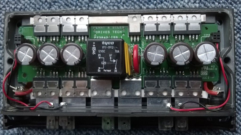
As far as current sensing, I'd hazard a guess the two devices in the middle on the lower row are either resistive shunts or hall-effect sensors
Re: Rebuild BM2 green...
Posted:
04 Feb 2016, 21:07by Burgerman
No. Those just go to the relay. And that would do what the roboteq does and sense battery current?
Re: Rebuild BM2 green...
Posted:
04 Feb 2016, 21:16by Irving
Burgerman wrote:No. Those just go to the relay. And that would do what the roboteq does and sense battery current?
yes, I can see that now. Might not be sense resistors but just some carefully sized PCB tracks..
still can't see where that info was written, must get new glasses

Re: Rebuild BM2 green...
Posted:
04 Feb 2016, 21:18by steves1977uk
Re: Rebuild BM2 green...
Posted:
04 Feb 2016, 21:28by Irving
Are those the actual devices?
OK, slightly better than I expected 11millohm at junction temp of 20degC, so about 17milliohm at working temp. Still nowhere near the best available
Re: Rebuild BM2 green...
Posted:
04 Feb 2016, 21:44by steves1977uk
It's just a general specshet on the IRF1010N. If these were replaced, what would be a better replacement?
Steve
Re: Rebuild BM2 green...
Posted:
04 Feb 2016, 23:43by Burgerman
http://www.eurotech.co.uk/dynamic/detai ... +RECTIFIERWould safely allow more power. But the controller somehow senses output current. So power would be limited to 50A regardless. So you would need to swap ALL the power mosfets, and find the two current sensors and fool them.
Re: Rebuild BM2 green...
Posted:
05 Feb 2016, 12:26by Irving
The ones BM linked to, or a host of others. The key parameter after on resistance, drain-source voltage and continuous drain current, is input capacitance. If its massively bigger the driving circuit might not be able to turn the MOSFET on fully/fast enough which would be self-defeating. If I was going to upgrade my controller I'd want to put a scope on it on the bench first to see the pulse timing before choosing a replacement device.
Its possible there is no current limit sensing, just temperature sensing for rollback, in which case replacing the MOSFETs with ones that run cooler will increase the output capability anyway.
Re: Rebuild BM2 green...
Posted:
05 Feb 2016, 13:22by Burgerman
When you set "turn rate" to 20% at max stick, by way of an e.g; thats what you get. A 20% pulsewidth to zero turn - provided motor compensation is off or set to zero. OR if theres no physical loading..
That means a motor with a stall current of 100A will only pull 20A from the battery, so the chair will not zero turn.
What you actually get, if you turn motor compensation up to the correct value, is 100A even with a 20% input command (if needed), to initiate this zero turn. So *something* is definitely measuring current! Quite what, I have no idea. But there are a lot of small chips on that board that are copied on each side. No doubt one of those is reading mag field or something (hall) somewhere.
Theres another issue with upgrading past 100A though. The daft connectors they use, and the way that the current is sent to the wiring by pushing the tabs against the terminals with a foam rubber strip! That would need at least bolts, and better soldered wiring.
Re: Rebuild BM2 green...
Posted:
07 Feb 2016, 14:21by Irving
The current sense would generally be either between ground and the source leads of the MOSFETs making up the lower half of the H-bridge or in the output lead to the motor. Either way its in a high current area so unlikely to be a small component.
Burgerman wrote:... So *something* is definitely measuring current! Quite what, I have no idea. But there are a lot of small chips on that board that are copied on each side. No doubt one of those is reading mag field or something (hall) somewhere...
Re: Rebuild BM2 green...
Posted:
07 Feb 2016, 16:44by LROBBINS
A shunt can also be a piece of wire with just enough resistance to give a measurable voltage drop - the charger I'm using does its current sensing that way. Ciao, Lenny
Re: Rebuild BM2 green...
Posted:
08 Feb 2016, 13:44by Irving
LROBBINS wrote:A shunt can also be a piece of wire with just enough resistance to give a measurable voltage drop - the charger I'm using does its current sensing that way. Ciao, Lenny
That's why I suggested it might be the PCB track between the source pins of the lower MOSFETs and the ground bus/plane. Its easy to control the 'resistance' of that and you only need one or two tenths of a volt, so we're looking at 2milliohm.
Incidentally, while perusing MOSFETs for my controller, I found some that have a built-in current sense connection; e.g. NXP's BUK7909-75AIE (75v, 75A, 8mOhm) gives a current out that's 1/500 of the drain current, so a 10ohm resistor to ground gives a 1.5v signal at 75A which makes it easy to sample with an ADC input on a microcontroller with no additional circuitry.
Re: Rebuild BM2 green...
Posted:
10 Feb 2016, 17:56by Burgerman
Battery fits... Thats a work of art!
Now sort wiiring, lights, and the fan controlled by the recently installed thermostat, and make a footrest...
Re: Rebuild BM2 green...
Posted:
10 Feb 2016, 20:47by rustyjames
Wow, that is a work of art, and coming along nicely.
Re: Rebuild BM2 green...
Posted:
10 Feb 2016, 21:47by hank

Pimp my Ride.
Will look well with that new seat back fitted.

Re: Rebuild BM2 green...
Posted:
10 Feb 2016, 22:03by Burgerman
And go well. As long as the seat back isnt narrower than my body...
This should have an enormous range. Will will hind out in about 10 days.
Re: Rebuild BM2 green...
Posted:
10 Feb 2016, 23:16by Burgerman
Better pics
Seat isnt bolted on, just loose. Wires all over the place. But you get the idea. Waiting for seat, and need to build a footplate. Then ready to go.
http://zoomability.com/zoom/ this gets 25 miles with just 950 watt hours. Mine isnt as efficient, as its not brushless. But I have 3200 watt hours... So should get 50 to 60 miles on a smooth pavement.
Re: Rebuild BM2 green...
Posted:
11 Feb 2016, 14:06by Burgerman
Seat plate on temporarily.
You can see the 100A PG power module here. The one I fitted a fan thermostat switch inside. This will be
fan cooled above 45 degrees C.
iI always get the flat seat plate powder coated too. Leaving it super glossy. Cushion (Jay2) is held in place via VELCRO. This seat plate will have 2x 2 inch wide velcro strips added. But first we need to wait for my car seat back to arrive...
Battery sides will be covered in 1mm black plastic sheet, slid into the base to hide the cells and wiring. You will only see the blue ones at the front.
LED 10 WATT headlamps (4x 25mm Diameter to be added) and they are as good as a car headlight, and really small!
Re: Rebuild BM2 green...
Posted:
11 Feb 2016, 16:40by expresso
Very nice -
Re: Rebuild BM2 green...
Posted:
11 Feb 2016, 22:40by Burgerman
My cooling fan works, but its a bit noisy. Doesent like 24V... What resistor would I need to slow it to a sensible rate... Takes .2A at 12V.
Re: Rebuild BM2 green...
Posted:
11 Feb 2016, 22:59by expresso
or just get a quiet fan - I changed out my fans in my power amps when i got it - too noisy for me - i dont like to hear anything when listening to music or movies - classical etc, -
i found the same fan at digitech - same size very quiet but moved just about the same CFM as the other fan - so i changed it and and cant hear it any more - which ever way is easier i guess for you -
Re: Rebuild BM2 green...
Posted:
12 Feb 2016, 00:12by LROBBINS
60 ohm, 5 W should do it - but you'll be dissipating ca. 2.5W as heat (but only when the fan is running). 68 ohm is, I think, the closest standard value. Ciao, Lenny
Re: Rebuild BM2 green...
Posted:
12 Feb 2016, 02:15by Burgerman
Thanks, must have one somewhere. I have a bunch of 5 and 10 watt resistors.
Expresso, you missed that its on 24V!
Re: Rebuild BM2 green...
Posted:
12 Feb 2016, 02:16by Burgerman
Thanks, must have one somewhere. I have a bunch of 5 and 10 watt resistors.
Expresso, you missed that its on 24V! Sounds like a vacuum cleaner!
Re: Rebuild BM2 green...
Posted:
12 Feb 2016, 02:37by ex-Gooserider
You will be wasting most of the light output of the LED's if you don't use the same LED color as the lenses - I.e red ones w/ red lenses and yellow ones w/ yellow lenses... The lenses are filters and BLOCK any light that isn't their color, so all that gets through is the part of the LED output that matches the lens, and whatever extra from the lens not being a 'perfect' filter....
If you put red LED's behind a yellow lens you will get dim light at best, and might not even be able to see it at worst....
White LED's will be brighter since they have SOME yellow light output, but really you want either Yellow LED's or to change the lenses to red (if possible)
Unless your local laws don't allow it (where do any light rules on blinking lights say "wheelchair" officer?) I'd make the yellow lights into blinkers, ideally alternating - MUCH more noticeable than just adding more steady red, and that is your main objective....
Burgerman wrote:Convert rear light to LED
Red LEDs in the red, white ones in the turn lights... I have ordered some red ones for those too. Because I have no need of turn signals. They will light up red!
So Projector lamps for the front. And this F55 one for the rear (because I like it) but turned to LED. I may not fit it. Depends on the seat... Might use red projector LEDs on the rear instead. Right now its taking 3 watts at 16 volts... So the 3kwh battery would run it for 44 and a half days.
ex-Gooserider
Re: Rebuild BM2 green...
Posted:
12 Feb 2016, 02:45by ex-Gooserider
Burgerman wrote:Trans MOSFET N-CH 55V 85A 3-Pin(3+Tab) TO-220AB
Does it help?
Where is the sense resistor?
That is not a part number, just a mechanical electrical spec that could apply to a huge number of parts... You need the actual part number that SHOULD be screened on the front (non-tab) side of the part. (note that while each pair should have the same number, different pairs may have different part numbers and be different parts)
The given spec says it's an N-channel part, rated for 55V max Drain / source voltage, and 85A current, in a TO-220AB physical package (defines the size and shape of the part, pin spacing, etc. but not necessarily the pin assignments)
You need the actual part numbers, and then use those to look up the manufacturer data sheets (which WILL be on-line)
ex-Gooserider