Dynamic Controls Power chair, RC Boat trailer project

Power wheelchair board for REAL info!

POWERCHAIR MENU! www.wheelchairdriver.com/powerchair-stuff.htm

Re: Dynamic Controls Power chair, RC Boat trailer project

Postby gcebiker » 10 Aug 2017, 09:52

Radio Control - Arduino Shark Bus Emulator for the Dynamic Shark Power Wheelchair Controller
Just in case you have not been following the other thread, Sir Mike from Canada was able to get me started with Eagle CAD and we now have Two Versions available.

From the other thread...


Blue boards work great...once i put the jumper in.

I have 18 spare boards, 9 of the Yellow and 9 of the Blue.

Anyone in Australia Wanting one, partially populated (resistors, IC sockets), i wont be able to post with the caps soldered in but will include them in the parcel.
$25 delivered with signature - Australia Only


Yellow have the larger holes on the input / output sides of the Arduino, larger holes for power resistor.
Image


Blue is better laid out, corrected hole sizes, i will put the wire link in as well as the other minor components for anyone wanting one.
Image


I have enough components to fully build up and test 5 Blue Boards if anyone wants a completed version, you will have to supply your own RC unit and wiring.
P.O.A

Posting to Overseas....OMG, From Australia...postage its expensive, on the upside, our Dollar is rubbish...so its like 75% off , prices i have listed are in AUD.
Probably still cheaper to just order 10 from DirtyPCB

Next version (not available as yet, till testing can be done on the Raspberry Pi Sections SirMike is interested in/requested)
Ver 3.25 has the power to the Arduino fixed, a link/place for putting a switch should you want to leave it connected but turned off.
Ver3.25.png


Amendments to the code would also enable this to remain connected and able to remotely turn the Radio Control Sections On/Off the same as Woodys JC2000 Joystick RC Arduino Bluetooth Smart Phone Version is able to do for the VSI style joysticks or if you prefer the WJJRCABS, maybe one of you military types might be able to come up with a harder to remember acronym ?

My YouTube Channel is 'gcebiker' a few videos there of this build process, first the Wii Remote Control for the Power Chair i built
In later videos i am using it with a PPM 2.4Ghz RC Transmitter from Hobby King to move my boat out the street so i can connect it to the car.

There is a seat on the Power chair / Boat tower so that it can carry me and the boat.
The Seat is on a swivel so i can watch where i am going with out having to twist around. The same seat then comes off and can go into the boat for use.
http://greenmobility.com.au/rc-wheelchair-controller/
My YouTube Ch -- https://www.youtube.com/user/gcebiker
User avatar
gcebiker
 
Posts: 879
Joined: 11 Jul 2015, 14:20
Location: Gold Coast, Queensland, Australia.

Re: Dynamic Controls Power chair, RC Boat trailer project

Postby gcebiker » 12 Feb 2018, 13:45

Squid season back again...figured i best put the Shark joystick EMU in a box properly.

Some pictures of the assembly today.
Factory Shark Bus cable used

Tony Matthews Shark Joystick EMU 3.jpg


Tony Matthews Shark Joystick EMU 1.jpg


Tony Matthews Shark Joystick EMU 2.jpg

Blue jumper on the lower of this picture is for supply of 5v to the Arduino Nano V3.0
A switch may be wired into here for turning off the EMU while not in use. :joint
http://greenmobility.com.au/rc-wheelchair-controller/
My YouTube Ch -- https://www.youtube.com/user/gcebiker
User avatar
gcebiker
 
Posts: 879
Joined: 11 Jul 2015, 14:20
Location: Gold Coast, Queensland, Australia.

Re: Dynamic Controls Power chair, RC Boat trailer project

Postby gcebiker » 22 Feb 2018, 01:16

PolyCraft Tough Tender / Gal trailer/ Yamaha 6hp 4 stroke motor just slightly too heavy for a round trip to the ramp and back.
... trying again with a Hobie Pro Angler 14 - Sail kit and Electric motor.

s-l16003small.jpg
http://greenmobility.com.au/rc-wheelchair-controller/
My YouTube Ch -- https://www.youtube.com/user/gcebiker
User avatar
gcebiker
 
Posts: 879
Joined: 11 Jul 2015, 14:20
Location: Gold Coast, Queensland, Australia.

Re: Dynamic Controls Power chair, RC Boat trailer project

Postby Scout » 23 Feb 2018, 08:52

gcebiker wrote:Next version (not available as yet, till testing can be done on the Raspberry Pi Sections SirMike is interested in/requested)
Ver 3.25 has the power to the Arduino fixed, a link/place for putting a switch should you want to leave it connected but turned off.


A few constructive criticisms re: layout (none are deal-breakers):
  • pick a single orientation for your components (even if it makes the layout a bit harder). I.e., all chips facing the same way, pin 1's always pointed the same way, '+' terminals of polarized components (caps, diodes) facing the same direction
  • consider using a square pad to make "pin 1" (or '+', etc.) more readily identifiable
  • consider adding reference designators (instead of component part numbers) to the silkscreen. How would you reference the "top diode" if trying to describe something to someone else ("While holding the board with the power connector on the right-hand side, component side exposed, the diode closest to the top edge of the board...")
  • add one (or more) tie-points for "ground" to make connecting a 'scope probe (or DMM "common" lead) easier. You can stuff a stiff piece of wire into the pad to make it easier to clip onto during testing
  • leave a larger "keep out" zone around mounting holes. Imagine putting metal (conductive) fasteners in/under those holes and wondering if you'll have to ADD an insulating (nylon) washer to prevent unintended shorts
  • consider surrounding (one or more) mounting holes with "ground" if you want to be able to electrically tie the board's ground to your chassis/enclosure
  • try to run stubs off to individual pads instead of routing a trace "across" a pad (i.e., imagine how you would isolate the - conductor of the eCap from the "ground" signal that runs through that pad vs. how you'd isolate pin 5 of the MAX485 from that same signal
  • leave as much space as possible for mounting components (e.g., that resistor near the MAX485 could probably benefit from a wider separation between mounting holes -- unless you want to mount it "on end" <frown>); ditto the two diodes
  • traces on the underside of the board are usually easier to follow while troubleshooting a circuit ("Where else does this signal go?")

Keep in mind that the silkscreen is only visible from one side of the board (you can pay for screens on both sides -- or, NONE!). So, when you're soldering -- or PROBING! -- components from the underside of the board, you have to make a special effort to keep track of which specific pin you're looking for (a "convention" makes it easier to avoid mistakes -- esp when you're frustrated trying to trace down a problem). And, if the installed component COVERS the silkscreen legend for that component, its hard to verify that the component is installed properly and sort out which lead is which.

[I have no idea of the purpose for the large "heavily perforated" area to the left side of the board; perhaps a "breadboarding" area?]
Scout
 
Posts: 71
Joined: 23 Nov 2017, 21:29
Location: USA

Re: Dynamic Controls Power chair, RC Boat trailer project

Postby Scout » 23 Feb 2018, 09:25

Again, some comments on "style":

gcebiker wrote:
Code: Select all
 {
      directionPotVal = analogRead(directionPot);
     
      directionPotVal = constrain(directionPotVal, 1, 1023);// Constrain to real numbers. 0 and 1024 are out of range for the controller.
      direction = map(directionPotVal, 0, 1024, 1, 1023); //here in case direction is inverted in wiring
      if (direction > 312 && direction < 712)                   // set dead zone of joystick
        direction = 512;
    }
    {
      speedPotVal = analogRead(speedPot);
      speedPotVal = constrain(speedPotVal, 1, 1023);    // Constrain value to real numbers.
      speed = map(speedPotVal, 0, 1024, 1023, 1 );  // here in case of speed is inverted in wiring
      //speed dead zone mapping
      if (speed > 312 && speed < 712) // set dead zone of joystick
        speed = 512;
    }


Numeric constants are A Bad Idea in almost all cases. They force the reader (who may not be you -- or, who may be you 6 months from now!) to wonder what they mean and where they came from. And, as most folks are lazy in terms of chasing down API details and RE-verifying the proper values for any particular instance of a function invocation, it is likely that you (or "he") will convince yourself of what you THINK a parameter means and gloss over an error that would otherwise be more visible.

E.g., (my guesstimates as to what your code is doing, based on what I think it SHOULD be doing):

Code: Select all
 {
      directionPotVal = analogRead(directionPot);

#define MIN_DIRECTION_POT (1)    // '0' is out of controller's range
#define MAX_DIRECTION_POT (1023)  // '1024' is out of controller's range
     
      directionPotVal = constrain(directionPotVal, MIN_DIRECTION_POT, MAX_DIRECTION_POT);// Constrain to valid numbers. Others are out of range for the controller.

#define MIN_DIRECTION (0)  // minimum value of "direction" variable
#define MAX_DIRECTION (1024)  // maximum value of "direction" variable

      direction = map(directionPotVal, MIN_DIRECTION, MAX_DIRECTION, MIN_DIRECTION_POT, MAX_DIRECTION_POT); //here in case direction is inverted in wiring

#define DIRECTION_CENTERED ((MAX_DIRECTION - MIN_DIRECTION)/2)
#define DIRECTION_DEADBAND (400)      // width of deadband in "direction" units

#define DIRECTION_LOW_DEADBAND (DIRECTION_CENTERED - DIRECTION_DEADBAND/2)
#define DIRECTION_HIGH_DEADBAND (DIRECTION_CENTERED + DIRECTION_DEADBAND/2)

      if ( (direction > DIRECTION_LOW_DEADBAND)
        && (direction < DIRECTION_HIGH_DEADBAND) )
        direction = DIRECTION_CENTERED;    // treat direction as "centered" if within deadband
    }

[...]


I'd question why the need to "constrain" these values. What could cause an "invalid" value (needing to be constrained)? Wouldn't that also be indicative of Something Wrong, somewhere? If that's the case, then you really want to be trapping those conditions and doing something about them (like signalling an error). If they "can't happen", but DO happen, then you're reasoning is either defective OR something unexpected has happened! AND, you probably want to know about either of these cases!

I've no idea whether these functions are part of a support library or things you crafted, yourself. But, with that many parameters, it gets hard to remember what order they are expected in the argument list. For example, these are all potentially valid prototypes for a "map" function:

Code: Select all
      map(value, minimum_range, maximum_range, minimum_domain, maximum_domain);
      map(value, minimum_domain, maximum_domain, minimum_range, maximum_range);
      map(value, minimum_range, minimum_domain, maximum_range, maximum_domain);
      map(value, maximum_range, minimum_range, maximum_domain, minimum_domain);
[...]


This is particularly important when more than one author is involved in a codebase (e.g., one library author may have a different set of conventions than the author of another library -- and both may have a different set of conventions than the primary application author(s)!)
Scout
 
Posts: 71
Joined: 23 Nov 2017, 21:29
Location: USA

Re: Dynamic Controls Power chair, RC Boat trailer project

Postby LROBBINS » 23 Feb 2018, 09:48

I think that Scout's comments are well taken, but would be cautious about one suggestion:
consider surrounding (one or more) mounting holes with "ground" if you want to be able to electrically tie the board's ground to your chassis/enclosure

IF the chassis/enclosure is not isolated from the chair framework, you have now created a low-impedance connection between ground and the chair frame. If ground is also B-, that is a direct connection of the battery negative to the frame. That is an absolute NO NO for wheelchairs - unlike a car where the driver can usually run away if there's a fire, a WC user usually cannot.

I would also consider going to an SMD version. I was leery of doing that, but discovered that SMD is actually easier and faster to do than through hole, and it doesn't really take any expensive equipment for small runs. I use: (1) an ordinary toaster-oven and watch with sweep second hand, (2) very fine solder that I flatten and cut into pieces that I stick to the board with good (sticky) flux, and (3) a stereo microscope and fine tweezers for manual pick and place. A good, large magnifying glass or magnifier headset would do as well, but I already had the scope. Placing the components is the trickiest part for my old hands, but once that's done the whole board is reflow soldered in a matter of minutes. Sure, if I had a lot to do a pick-and-place robot, a real reflow oven, stencils and fresh solder paste would make it even easier, but for a few small to medium sized boards at a time, my crude setup works pretty well - once in a while I have to fix a component that "gravestones" during reflow, but I've only once had a solder bridge and only once had a cold joint. I've fu'ed point-to-point wiring a lot more often.
LROBBINS
 
Posts: 5553
Joined: 27 Aug 2010, 09:36
Location: Siena, Italy

Re: Dynamic Controls Power chair, RC Boat trailer project

Postby gcebiker » 23 Feb 2018, 14:37

Its all mirrored from the Dynamic Controls wiring,

I have already said...this is my first Arduino code, others are welcome to mod it.
Its been posted publicly for just this reason.

Also my first board, please do build on the work i have done to improve it.
This is iteration 3.25
Ver3.25.png


This is Ver 3.23
v3.23.png


It will benefit the whole community.
In real world application i found i needed to make code tweaks, videos on YouTube 'gcebiker' , May clear it up.

As it is presently is, its working very very well but the load on the chair (pulling a boat and myself up a boat ramp) is not possible with the current power base and current limitations i am working with.

Thus i have reduced the load i am asking the chair to pull and moved to a Hobie Kayak for this Squid season.

I may make a smaller version that is not Pi compatible but have not bothered as yet as this board is able to be cut up if needed.

Scout,
Please make the code alterations as you see fit and upload, i will be happy to test it on the EMU if you don't have one built up.

Cheers
Tony
http://greenmobility.com.au/rc-wheelchair-controller/
My YouTube Ch -- https://www.youtube.com/user/gcebiker
User avatar
gcebiker
 
Posts: 879
Joined: 11 Jul 2015, 14:20
Location: Gold Coast, Queensland, Australia.

Re: Dynamic Controls Power chair, RC Boat trailer project

Postby gcebiker » 23 Feb 2018, 14:49

Scout wrote:
gcebiker wrote:Next version (not available as yet, till testing can be done on the Raspberry Pi Sections SirMike is interested in/requested)
Ver 3.25 has the power to the Arduino fixed, a link/place for putting a switch should you want to leave it connected but turned off.


A few constructive criticisms re: layout (none are deal-breakers):
  • pick a single orientation for your components (even if it makes the layout a bit harder). I.e., all chips facing the same way, pin 1's always pointed the same way, '+' terminals of polarized components (caps, diodes) facing the same direction
  • consider using a square pad to make "pin 1" (or '+', etc.) more readily identifiable
  • consider adding reference designators (instead of component part numbers) to the silkscreen. How would you reference the "top diode" if trying to describe something to someone else ("While holding the board with the power connector on the right-hand side, component side exposed, the diode closest to the top edge of the board...")
  • add one (or more) tie-points for "ground" to make connecting a 'scope probe (or DMM "common" lead) easier. You can stuff a stiff piece of wire into the pad to make it easier to clip onto during testing
  • leave a larger "keep out" zone around mounting holes. Imagine putting metal (conductive) fasteners in/under those holes and wondering if you'll have to ADD an insulating (nylon) washer to prevent unintended shorts
  • consider surrounding (one or more) mounting holes with "ground" if you want to be able to electrically tie the board's ground to your chassis/enclosure
  • try to run stubs off to individual pads instead of routing a trace "across" a pad (i.e., imagine how you would isolate the - conductor of the eCap from the "ground" signal that runs through that pad vs. how you'd isolate pin 5 of the MAX485 from that same signal
  • leave as much space as possible for mounting components (e.g., that resistor near the MAX485 could probably benefit from a wider separation between mounting holes -- unless you want to mount it "on end" <frown>); ditto the two diodes
  • traces on the underside of the board are usually easier to follow while troubleshooting a circuit ("Where else does this signal go?")

Keep in mind that the silkscreen is only visible from one side of the board (you can pay for screens on both sides -- or, NONE!). So, when you're soldering -- or PROBING! -- components from the underside of the board, you have to make a special effort to keep track of which specific pin you're looking for (a "convention" makes it easier to avoid mistakes -- esp when you're frustrated trying to trace down a problem). And, if the installed component COVERS the silkscreen legend for that component, its hard to verify that the component is installed properly and sort out which lead is which.

[I have no idea of the purpose for the large "heavily perforated" area to the left side of the board; perhaps a "breadboarding" area?]

Its not a commercial board...
The rest of it is for a Pi Hat, someone else designed...I have no idea about Pi's or their Hat's

Please do redesign it in Eagle and share the board,
As you say best practice is many things i have not done with my first attempt at this.

I look forward to your contributions.
Cheers
Tony
http://greenmobility.com.au/rc-wheelchair-controller/
My YouTube Ch -- https://www.youtube.com/user/gcebiker
User avatar
gcebiker
 
Posts: 879
Joined: 11 Jul 2015, 14:20
Location: Gold Coast, Queensland, Australia.

Re: Dynamic Controls Power chair, RC Boat trailer project

Postby Scout » 23 Feb 2018, 18:03

gcebiker wrote:
Next version...

Its not a commercial board...
The rest of it is for a Pi Hat, someone else designed...I have no idea about Pi's or their Hat's


Understandable. I only offered my comments as "tips" for your own personal edification (ooo! now THAT's a big word! :D) Again, please don't take them as criticisms (I made all of the holes too small on the first board I had built -- because I had neglected to account for the plating! banghead )

Please do redesign it in Eagle and share the board,


Sorry, but I don't use Eagle (I use OrCAD/Cadence and Protel/Altium).
Scout
 
Posts: 71
Joined: 23 Nov 2017, 21:29
Location: USA

Re: Dynamic Controls Power chair, RC Boat trailer project

Postby Scout » 24 Feb 2018, 07:50

LROBBINS wrote:I think that Scout's comments are well taken, but would be cautious about one suggestion:
consider surrounding (one or more) mounting holes with "ground" if you want to be able to electrically tie the board's ground to your chassis/enclosure

IF the chassis/enclosure is not isolated from the chair framework, you have now created a low-impedance connection between ground and the chair frame. If ground is also B-, that is a direct connection of the battery negative to the frame. That is an absolute NO NO for wheelchairs - unlike a car where the driver can usually run away if there's a fire, a WC user usually cannot.


The advantage to grounding the enclosure is that it helps cut down on radiated noise. If you're a manufacturer, you can afford to have PLASTIC enclosures that are coated with conductive paint on the inside.

I would also consider going to an SMD version. I was leery of doing that, but discovered that SMD is actually easier and faster to do than through hole, and it doesn't really take any expensive equipment for small runs. I use: (1) an ordinary toaster-oven and watch with sweep second hand, (2) very fine solder that I flatten and cut into pieces that I stick to the board with good (sticky) flux, and (3) a stereo microscope and fine tweezers for manual pick and place. A good, large magnifying glass or magnifier headset would do as well, but I already had the scope. Placing the components is the trickiest part for my old hands, but once that's done the whole board is reflow soldered in a matter of minutes. Sure, if I had a lot to do a pick-and-place robot, a real reflow oven, stencils and fresh solder paste would make it even easier, but for a few small to medium sized boards at a time, my crude setup works pretty well - once in a while I have to fix a component that "gravestones" during reflow, but I've only once had a solder bridge and only once had a cold joint. I've fu'ed point-to-point wiring a lot more often.


I would recommend AGAINST doing it -- esp for a hobbyist market. Few people can really do SMT work reliably -- esp if they are doing "one off". When I assemble SMT prototypes, I prefer to do component-at-a-time with a Leister (Image -- they don't sell my 30 year old unit anymore but this gives a rough idea; blower is in a separate box on the other end of that black hose). It's just too hard to get ALL the components in place (without adhesive) and then bake the complete board. By soldering one at a time, I don't have to worry about accidentally bumping a previously placed component and knocking it out of position.

I use solder paste (comes in a 10cc syringe) with a manual "paste gun" ("DispensGun" -- also, too old to still be offered for sale) and choose a "needle" (nozzle?) of appropriate diameter to the bead of solder I want to lay down. More labor intensive than a stencil but saves me the trouble of having stencils cut!

To see what I'm doing, I use a "Flipperport" autofocus camera with LCD goggles Image or an old B&L stereoscopeImage 
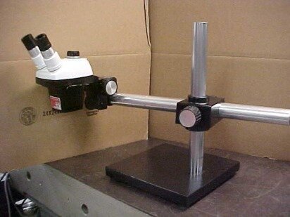
on a long mounting arm (though mine is black). The Flipperport is nice as I can keep my face away from any fumes coming off the board -- I can even look in a different direction as the goggles are wed to my eyes! Not possible with the stereomicroscope that must hover above the work.

The other problem with SMT is servicing/repairing an existing board that develops a fault, down the road. Chances are, you laid out the board "tight" (or, at least, tighter than you would have with thru-hole) and now you've got to work in those cramped quarters to try to remove a component without screwing up any of the surrounding bits of kit.

Given that Tony's board is largely defined by the MCU module and the attendant connectors/connections, I don't think he's going to save much by going to an SMT fab. If I have to make more than one of an item, I'll just hire it out to someone (or, "tap" a friend in the business) who can knock it off in no time. By contrast, I have no problem building small lots of thru-hole designs -- it's almost therapeutic to stuff the boards, flip them over and then touch all the pads with some solder!
Scout
 
Posts: 71
Joined: 23 Nov 2017, 21:29
Location: USA

Re: Dynamic Controls Power chair, RC Boat trailer project

Postby LROBBINS » 24 Feb 2018, 10:48

The advantage to grounding the enclosure is that it helps cut down on radiated noise. If you're a manufacturer, you can afford to have PLASTIC enclosures that are coated with conductive paint on the inside.

Of course, but for a wheelchair that means having separate signal and power grounds with DC isolation between them - hence just bolting through a ground pad is not a good idea. In my system the enclosures are indeed metal and they form part of the signal ground, but B- is isolated from that by a 10 uF ceramic cap in each module and/or in each DB connector. The Roboteq controller also has logic ground isolated from the case - I don't know if they have any noise bypass between them, but I've added caps on the DB connectors there as well.

Maybe I'm just lucky, but I've not had any reliability problems with my SMD boards. Being a novice, I started with large components (805) and uncrowded layout, but now have no trouble with much smaller components, though I still leave lots of room, large, low aspect ratio vias etc. The flattened wire solder has an advantage over paste in that it can't roll and the sticky flux keeps the components in place as I move the board from scope to oven with flat forceps. Re-work hasn't been difficult - until the boards get conformal coated! I more often use an old army-surplus Weller mechanically-thermostated iron with modified tips for re-work rather than the air wand. For example, I have a chisel tip notched so that it has two mini-chisels that match 805 spacing. I think I use the air wand most often for shrinking heat shrink. If you would like to see the boards and the programming, you can download everything at https://drive.google.com/open?id=0B3svXvyPGRgral9FU2lJZlpHdFU
LROBBINS
 
Posts: 5553
Joined: 27 Aug 2010, 09:36
Location: Siena, Italy

Re: Dynamic Controls Power chair, RC Boat trailer project

Postby Scout » 25 Feb 2018, 19:54

gcebiker wrote:<photo of powerchair towing boat trailer>


Hmmm... this is novel/interesting/amusing. I will have to think if there is any sort of similar use that I can come up with to justify making space to keep a chair (or, a chair's chassis!) here. No boat (nor interest in maritime activities) so it will have to be something terrestrial.

I'd have thought you'd want larger drive wheels for navigating uneven terrain -- or, are all your boat ramps "paved" (cement)? And, does the chair have enough mass to actually give the tires enough frictional pulling capability? Maybe make a mount for the "outboard" to be stowed on the chair (and serve as ballast) while towing the boat?
Scout
 
Posts: 71
Joined: 23 Nov 2017, 21:29
Location: USA

Re: Dynamic Controls Power chair, RC Boat trailer project

Postby Scout » 25 Feb 2018, 21:15

LROBBINS wrote:Maybe I'm just lucky, but I've not had any reliability problems with my SMD boards.


If I'm doing something JUST FOR ME, then I can make decisions that only I have to live with. OTOH, if I am doing something that I expect to share with others -- or, that others will be called on to maintain -- then I have to limit my choices to things that are appropriate for that wider audience. E.g., it won't do Tony any good if I make modifications to his code -- but in LISP or Haskell or... Similarly, his choice of an rPi/Arduino limits the help that I can provide him -- because I have no desire to tinker with either of those platforms given that I have other more capable platforms and tools at my disposal.

So, while you may have "good luck", you have to consider that "others" may not: what will happen if someone connects power to the board "backwards" or stuffs a component backwards or shorts out two pins while troubleshooting a problem? :o

[Sockets were invented for a reason :) ]
Scout
 
Posts: 71
Joined: 23 Nov 2017, 21:29
Location: USA

Re: Dynamic Controls Power chair, RC Boat trailer project

Postby gcebiker » 26 Feb 2018, 03:09

Its silk screened...if you cant read or solder, the project is beyond your reach.
I am able to build them up / test for you.

Its is as accessible as it can possibly be, ....its cheap drunk2
http://greenmobility.com.au/rc-wheelchair-controller/
My YouTube Ch -- https://www.youtube.com/user/gcebiker
User avatar
gcebiker
 
Posts: 879
Joined: 11 Jul 2015, 14:20
Location: Gold Coast, Queensland, Australia.

Re: Dynamic Controls Power chair, RC Boat trailer project

Postby jacfger » 27 Feb 2018, 08:02

Hi guys, so recently my friend and I decided to spend some time to make a auto wheelchair. But I'm now stuck on interfacing the Arduino with wheel chair.
So, I have got respond from the wheel chair power core so I assume there's no big deal in the circuit. But I can't drive the wheelchair at all. The logic and calculation was made by you guys, I just based on your program and organize it a bit (organized from my perspective), but there's no luck on moving the wheel chair at all.
Then I borrow my friends logic analyzer, there's two problem I found. First one, the shark module was communicate with two stop bit. Second one, when I looked onto a normal joystick to power module communication, the power module respond was always the same even if the wheel chair is moving (I'm using a power supply so the power level won't change.) But in Arduino to power module case, when the module told the car to stop, everything's fine. But when I want it to move, it just respond with another string. So this is what my logic analyzer read. (21 a7 89 a0 8e 0f) And I obviously can tell the normal one is (21 88 80 80 D6 F) (21 87 80 80 d7 f). Also, I noticed there's a brake release sound when using the joystick, but not when I'm using Arduino. Is that anything worth noticing?
The first problem was an easy fix, but I wonder do you guys notice that because it wasn't shown in the program you guys had developed. But the second problem had trouble me for days.
Can anyone help me? So frustrated to this problem LOL. banghead

P.S. hope my English was good enough for you guys to understand
jacfger
 
Posts: 3
Joined: 27 Feb 2018, 07:41

Re: Dynamic Controls Power chair, RC Boat trailer project

Postby woodygb » 27 Feb 2018, 09:29

If it is any consolation I cannot get my Shark based wheelchair to move via the Arduino interface despite MANY attempts.

At the moment this project is temporarily abandoned until I can understand the reply from the module.


BTW ...I used a cheap USB-RS485 interface and use REALTERM to capture the RS485 comms .
https://www.ebay.co.uk/itm/USB-to-RS485 ... 3059316020
https://sourceforge.net/projects/realterm/

Display setting Uint8 , 2 bits , Sync NONE.
Port settings SELECT PORT , 38400 ,Parity NONE , 8 Bits ,Stop bits 2 ,Hardware flow control RS485 , CLICK ON CHANGE.

Below is the capture of the signal from the WORKING joystick to power module communication.
Realterm data capture from RS485

0 This indicates 24v pulse for 300ms +/- 20ms

116 130 140 132 128 130 165 160 128 178 15 Sent start sequence

Initial Controller Reply = 5 128 250 15

Then .........

column number Joystick Sent start with 96 : Controller Replies start with 33
0 1 2 3 4 5 6 7 8 9 : 0 1 2 3 4 5

96 193 192 255 223 128 140 128 180 15 33 128 128 192 158 15
OFF Data 6 = 140 & Reply Data 4 = 158

96 193 192 255 231 128 140 128 172 15 33 128 192 192 222 15
OFF Data 6 = 140 & Reply Data 4 = 222

96 193 192 255 231 128 132 128 180 15 33 128 192 192 222 15
96 193 192 255 223 128 132 128 188 15 33 128 192 192 222 15
96 193 192 255 231 128 132 128 180 15 33 128 192 192 222 15
96 193 192 255 223 128 132 128 188 15 33 128 192 192 222 15
96 193 192 255 223 128 132 128 188 15 33 128 192 192 222 15
96 193 192 255 231 128 132 128 180 15 33 128 192 192 222 15
96 193 192 255 231 128 132 128 180 15 33 128 192 192 222 15
96 193 192 255 230 128 132 128 181 15 33 128 192 192 222 15
8 OFF pulses Data 6 = 132 & Reply Data 4 = 222

96 193 192 255 222 128 132 128 189 15 33 128 128 192 158 15
96 193 192 255 222 128 132 128 189 15 33 128 128 192 158 15
96 193 192 255 222 128 132 128 189 15 33 128 128 192 158 15
96 193 192 255 222 128 132 128 189 15 33 128 128 192 158 15
96 193 192 255 222 128 132 128 189 15 33 128 128 192 158 15
96 193 192 255 222 128 132 128 189 15 33 128 128 192 158 15
96 193 192 255 230 128 132 128 181 15 33 128 128 192 158 15
96 193 192 255 222 128 132 128 189 15 33 128 128 192 158 15
96 193 192 255 230 128 132 128 181 15 33 128 128 192 158 15
96 193 192 255 230 128 132 128 181 15 33 128 128 192 158 15
96 193 192 255 222 128 132 128 189 15 33 128 128 192 158 15
96 193 192 255 222 128 132 128 189 15 33 128 128 192 158 15
96 193 192 255 223 128 132 128 188 15 33 128 128 192 158 15
96 193 192 255 222 128 132 128 189 15 33 128 128 192 158 15
96 193 192 255 223 128 132 128 188 15 33 128 128 192 158 15
96 193 192 255 222 128 132 128 189 15 33 128 128 192 158 15
96 193 192 255 222 128 132 128 189 15 33 128 128 192 158 15
96 193 192 255 223 128 132 128 188 15 33 128 128 192 158 15
96 193 192 255 223 128 132 128 188 15 33 128 128 192 158 15
96 193 192 255 223 128 132 128 188 15 33 128 128 192 158 15
96 193 192 255 223 128 132 128 188 15 33 128 128 192 158 15
21 OFF pulses Data 6 = 132 & Reply Data 4 = 158

96 193 192 255 222 128 132 128 189 15 33 146 128 192 140 15
96 193 192 255 223 128 132 128 188 15 33 146 128 192 140 15
96 193 192 255 223 128 132 128 188 15 33 146 128 192 140 15
96 193 192 255 223 128 132 128 188 15 33 146 128 192 140 15
96 193 192 255 223 128 132 128 188 15 33 146 128 192 140 15
96 193 192 255 223 128 132 128 188 15 33 146 128 192 140 15
96 193 192 255 222 128 132 128 189 15 33 146 128 192 140 15
96 193 192 255 222 128 132 128 189 15 33 146 128 192 140 15
96 193 192 255 222 128 132 128 189 15 33 146 128 192 140 15
Then Data 6 = 132 & Reply Data 4 = 140
An expert is a person who has made all the mistakes that can be made in a very narrow field.
Niels Bohr
User avatar
woodygb
 
Posts: 7070
Joined: 12 Mar 2011, 18:45
Location: Bedford UK

Re: Dynamic Controls Power chair, RC Boat trailer project

Postby jacfger » 27 Feb 2018, 10:18

ok good. More update. So I copy a stream of data record from moving the joystick till the brake release. And guess what, nothing happened!! Not exciting till I found a quite different respond from the power core. This time, the respond is 0x21 0x85 0x8b 0xa0 0xae 0x0f. Well, at least I get rid of the A at the 4 msb of the second byte.
jacfger
 
Posts: 3
Joined: 27 Feb 2018, 07:41

Re: Dynamic Controls Power chair, RC Boat trailer project

Postby woodygb » 27 Feb 2018, 10:38

Converted to decimal.

33 133 139 160 174 15

Go here:- http://gctek.me/dynamic-controls/shark/

Download data sheet.
An expert is a person who has made all the mistakes that can be made in a very narrow field.
Niels Bohr
User avatar
woodygb
 
Posts: 7070
Joined: 12 Mar 2011, 18:45
Location: Bedford UK

Re: Dynamic Controls Power chair, RC Boat trailer project

Postby woodygb » 27 Feb 2018, 11:00

Here is my NON WORKING Arduino start up ( Using Tony's start up sequence ) and the modules response.

96 193 192 255 240 128 132 128 171 15 : 33 178 137 192 227 15

I did try MY captured start up sequence ...but it didn't work either.
An expert is a person who has made all the mistakes that can be made in a very narrow field.
Niels Bohr
User avatar
woodygb
 
Posts: 7070
Joined: 12 Mar 2011, 18:45
Location: Bedford UK

Re: Dynamic Controls Power chair, RC Boat trailer project

Postby jacfger » 27 Feb 2018, 11:20

Woody, what circuit are you using to interface the wheelchair? Cause I'm now wondering if that's the problem.

Anyway, this is my boot up sequence.

74 82 85 82 80 88 cd a0 80 8d 0f and the respond is 05 80 fa 0f

Seems I have no trouble on booting it up.

*edit: oh wait, I see what you means... well, I mean even more weird problem lol. I didn't have such respond before. But I think you may check if your timing is correct though. You see, when I was using my logic analyzer, the Joystick controller timing differ is, at least in my case, is always -30micro second. 30 microsecond error in 20 millisecond period. lol. The respond from the power module did change after I switch millis() to micros(). But I still not sure if that's the problem till now.
jacfger
 
Posts: 3
Joined: 27 Feb 2018, 07:41

Re: Dynamic Controls Power chair, RC Boat trailer project

Postby woodygb » 27 Feb 2018, 12:48

Arduino Shark EMU schematic.jpg
An expert is a person who has made all the mistakes that can be made in a very narrow field.
Niels Bohr
User avatar
woodygb
 
Posts: 7070
Joined: 12 Mar 2011, 18:45
Location: Bedford UK

Re: Dynamic Controls Power chair, RC Boat trailer project

Postby gcebiker » 27 Feb 2018, 23:54

Woody, can you post a picture or model of your joystick / power module and your Arduino Code please ?
(or email the Arduino sketch...no point in someone using one that may have errors.)

I will load it onto mine and check for faults (hardware / software / timing ).
and compare the output with the logic analyzer.

My code emulates my Joystick, a REM01 (Pretty sure now i forgot to mention that explicitly ...anywhere, i will address that)

If you have a different Joystick with more functions and you use my start up sequence it will still work but will not enable the extra functions present in the Power Module.
http://greenmobility.com.au/rc-wheelchair-controller/
My YouTube Ch -- https://www.youtube.com/user/gcebiker
User avatar
gcebiker
 
Posts: 879
Joined: 11 Jul 2015, 14:20
Location: Gold Coast, Queensland, Australia.

Re: Dynamic Controls Power chair, RC Boat trailer project

Postby gcebiker » 28 Feb 2018, 00:16

Abbreviated my code is.
300ms Pulse High (of full battery volts, this is not a data pulse but a DG419 (maxim brand) voltage pulse)

- Then data
(your Start up packet you capture)
- a break

Then your joystick data
(if the joystick is not centered it wont start till it is '192')


No "off" pulse is needed, if the max timing is exceeded the Power Module will stop anyway, it will keep sending its own packets but wont "restart" till a new "startup" packet is sent from the Joystick.
http://greenmobility.com.au/rc-wheelchair-controller/
My YouTube Ch -- https://www.youtube.com/user/gcebiker
User avatar
gcebiker
 
Posts: 879
Joined: 11 Jul 2015, 14:20
Location: Gold Coast, Queensland, Australia.

Re: Dynamic Controls Power chair, RC Boat trailer project

Postby woodygb » 28 Feb 2018, 01:18

Hi Tony it is very early Shark DK-REMA06 ....the module itself is now obselete ...I will check the model number when it is daylight here.

The code is yours that you posted here and unmodified except for pin numbers as I'm using a Pro Mini.... I'll email you the code tomorrow.

I did try replacing your start up sequence with what I thought might be my start up code ... but nothing.

I checked the ON pulse timing with another Arduino and a bit of code and it was within the parameters.


Image
An expert is a person who has made all the mistakes that can be made in a very narrow field.
Niels Bohr
User avatar
woodygb
 
Posts: 7070
Joined: 12 Mar 2011, 18:45
Location: Bedford UK

Re: Dynamic Controls Power chair, RC Boat trailer project

Postby gcebiker » 28 Feb 2018, 03:56

Ill need the model of the Power module as well.(well probally not now that i think of it as the module will just ignore bits of start up code that its not capable of ..lights, etc)

If that is an attendant Joystick you will only need to enable the 'attendant BIT' to 'on' or what ever it is, tho that should be part of your captured start up packet ...mmm

Only thing i can think off is that you have A/B reversed but i bet that is the first thing you tried.

Non the less, i will load your code and try it on my emu to see what it outputs.
Can you cut and paste the bit of code you have changed (into a post) and i will put into my Nano code emu/test.
http://greenmobility.com.au/rc-wheelchair-controller/
My YouTube Ch -- https://www.youtube.com/user/gcebiker
User avatar
gcebiker
 
Posts: 879
Joined: 11 Jul 2015, 14:20
Location: Gold Coast, Queensland, Australia.

Re: Dynamic Controls Power chair, RC Boat trailer project

Postby woodygb » 28 Feb 2018, 11:29

Power module is a DK-PMA01
An expert is a person who has made all the mistakes that can be made in a very narrow field.
Niels Bohr
User avatar
woodygb
 
Posts: 7070
Joined: 12 Mar 2011, 18:45
Location: Bedford UK

Re: Dynamic Controls Power chair, RC Boat trailer project

Postby gcebiker » 28 Feb 2018, 13:02

Woody, your problem is with the Joystick data.

The power module is seeing that the joystick is not centered, just tweak the RC fine adjustment to get the read out to be 192, when stationary.

Column number Joystick Sent start with 96 : Controller Replies start with 33
0 1 2 3 4 5 6 7 8 9 : 0 1 2 3 4 5

96 193 192 255 223 128 140 128 180 15 33 128 128 192 158 15


That joystick code should be 96,192,192 ...else it throws an error.
I find that i cant get mine dead on, so i just start it and then 'tap' the joystick till i hear the brakes click...then its good to go.

Depends on the dead band how much it needs 'tapping'
http://greenmobility.com.au/rc-wheelchair-controller/
My YouTube Ch -- https://www.youtube.com/user/gcebiker
User avatar
gcebiker
 
Posts: 879
Joined: 11 Jul 2015, 14:20
Location: Gold Coast, Queensland, Australia.

Re: Dynamic Controls Power chair, RC Boat trailer project

Postby gcebiker » 28 Feb 2018, 13:17

If thats an issue for anyone,

Just send a 'fake' packet of Joystick data before the real data,

make a new function
eg Void fakeData () {

fill with fake data


Adjust the "Void Setup () {"
Code: Select all
// If 'off' turn 'on'
  // check state, if on/off button is pressed, change state to "ON" and run start up sequence.
  else if (onOffVal > 1500 && onOffState == LOW)
  {
    onOffState = !onOffState;     // toggle state to HIGH if in'off mode' and on/off button is pressed
    digitalWrite(led, onOffState); // turn on LED pin to get visual indication of on/off state
    sharkStartup();              // call function sharkStartup()

  }


To call the Fake data after the startup data
Code: Select all
// If 'off' turn 'on'
  // check state, if on/off button is pressed, change state to "ON" and run start up sequence.
  else if (onOffVal > 1500 && onOffState == LOW)
  {
    onOffState = !onOffState;     // toggle state to HIGH if in'off mode' and on/off button is pressed
    digitalWrite(led, onOffState); // turn on LED pin to get visual indication of on/off state
    sharkStartup();              // call function sharkStartup()
    fakeData ();   // call fake Joystick data packet so that the Power Module arms, to allow for 'dirty pots'
  }

:thumbup:
http://greenmobility.com.au/rc-wheelchair-controller/
My YouTube Ch -- https://www.youtube.com/user/gcebiker
User avatar
gcebiker
 
Posts: 879
Joined: 11 Jul 2015, 14:20
Location: Gold Coast, Queensland, Australia.

Re: Dynamic Controls Power chair, RC Boat trailer project

Postby woodygb » 28 Feb 2018, 14:05

The original Sharks joystick sends 193 on one channel and 192 on the other and starts up just fine.

I did try altering the R/C transmitter offsets and make it send EXACTLY 192 ...but nothing.
An expert is a person who has made all the mistakes that can be made in a very narrow field.
Niels Bohr
User avatar
woodygb
 
Posts: 7070
Joined: 12 Mar 2011, 18:45
Location: Bedford UK

Re: Dynamic Controls Power chair, RC Boat trailer project

Postby gcebiker » 01 Mar 2018, 04:55

Just to be sure, Woody the Arduino Pro Mini....
Are you using the 3.3v or the 5V model ?

Or are you powering the MAX485 and DG419J from a Traco Power 5V/12v Reg ?

Just trying to rule out brown outs.
http://greenmobility.com.au/rc-wheelchair-controller/
My YouTube Ch -- https://www.youtube.com/user/gcebiker
User avatar
gcebiker
 
Posts: 879
Joined: 11 Jul 2015, 14:20
Location: Gold Coast, Queensland, Australia.

PreviousNext

Return to Everything Powerchair

Who is online

Users browsing this forum: daveonwheels and 104 guests


  eXTReMe Tracker