Another off the wall question.
I ended up with a Segway pro and had it working as a mule to pull a manual chair.
I tried to go one better and move the motors to the chair, and extend the sensor and power leads.
I get an error that complains about the motor sensors.
The schematic for this controller have the sensors with a pull up to 5 volts.
I suspect that it does not like the leads being extended.
So the general question is:
If I am using a brushless motor with 3 hall effect sensors, what kind of wiring should I be using?
(twisted pair, shielded cable, or something else)
I am not expecting to have you answer the question about my odd ball Segway kluged setup. For now I am putting it back to standard configuration and will use it as a mule.
But I am considering a new build, and would use brushless motors and the controller from the builds on this site.
The problems I ran into got me thinking about that build, and was wondering how you folks have wired in the brushless sensors.
Thanks once again.
I may never get around to the build, but at least I wanted to learn so if I do that I can avoid problems.
anouther strange question on brushless motor sensors
16 posts
• Page 1 of 1
anouther strange question on brushless motor sensors
![]() by wilsonintexas » 15 Feb 2018, 01:33
by wilsonintexas » 15 Feb 2018, 01:33
- wilsonintexas
- Posts: 140
- Joined: 26 Aug 2014, 17:51
- Location: Dallas Texas
Re: anouther strange question on brushless motor sensors
![]() by Burgerman » 15 Feb 2018, 01:49
by Burgerman » 15 Feb 2018, 01:49
Unless the wiring is very long I would not expect that to be your problem. Going by hobby sensored motors, or the non screened invacare cables, etc. Its just hall chips, on off switching on most. So I suspect you have another problem.
-

Burgerman - Site Admin
- Posts: 65235
- Joined: 27 May 2008, 21:24
- Location: United Kingdom
Re: anouther strange question on brushless motor sensors
![]() by wilsonintexas » 16 Feb 2018, 04:59
by wilsonintexas » 16 Feb 2018, 04:59
Thanks,
I was not really looking to solve this one, but wanted to see what I should use for the next build.
Is a cat 5 Ethernet cable acceptable?
I picked it,
1) I had some
2) It had enough leads.
I was not really looking to solve this one, but wanted to see what I should use for the next build.
Is a cat 5 Ethernet cable acceptable?
I picked it,
1) I had some
2) It had enough leads.
- wilsonintexas
- Posts: 140
- Joined: 26 Aug 2014, 17:51
- Location: Dallas Texas
Re: anouther strange question on brushless motor sensors
![]() by Burgerman » 16 Feb 2018, 05:26
by Burgerman » 16 Feb 2018, 05:26
For the hall signal wires yes. Some systems use a sine wave signal from a magnet/coil sensor or a proportional rather than digital hall sensor or rather 3. Again it should be OK.
Usually, theres 3 big current wires.
3 signal or sensor output wires.
1 0V
1 5V
Usually, theres 3 big current wires.
3 signal or sensor output wires.
1 0V
1 5V
-
Burgerman - Site Admin
- Posts: 65235
- Joined: 27 May 2008, 21:24
- Location: United Kingdom
Re: anouther strange question on brushless motor sensors
![]() by Scout » 17 Feb 2018, 22:40
by Scout » 17 Feb 2018, 22:40
wilsonintexas wrote:I ended up with a Segway pro and had it working as a mule to pull a manual chair.
I tried to go one better and move the motors to the chair, and extend the sensor and power leads.
You couldn't, also, "remote" the controller from the segway?
I get an error that complains about the motor sensors.
The schematic for this controller have the sensors with a pull up to 5 volts.
Where did you find this schematic? Or, is it just a "wiring diagram"? A true schematic would provide clues as to how the data from the sensors were being interpreted.
I suspect that it does not like the leads being extended.
A more likely problem is that you screwed up in some way in extending them -- a bad solder joint, crossed wires, partial short, etc.
So the general question is:
If I am using a brushless motor with 3 hall effect sensors, what kind of wiring should I be using?
(twisted pair, shielded cable, or something else)
That depends on how the controller interprets the signals from the sensors. Note that a segway's controller has a different task than that of a powerchair -- it expects to be changing direction often and making short "backward" excursions as part of its balance algorithm. Powerchairs tend to go in one direction at a time. The motors tend to move with relatively constant/smooth acceleration -- you don't worry about the chair suddenly starting to tip backwards and the motor appearing to have moved the wrong way!
So, it may be that the Segway's controller (which is what you're dealing with, right?) looks at the edges of the feedback signals from the sensors and is more responsive to them (as earlier indicators of the actual position of the magnetic field) to help lead the commutation ("moving" of the fields). As such, noise on the signal can be interpreted as a valid edge (remember, the original designers intended the wiring harness to have a particular physical configuration -- that you've just altered!).
A company I worked for used feedback from the motor windings as an indirect indication of the armature's position (much like the hall effect sensors track the relative location of the magnetic field). This allowed us to maximize the acceleration profile of individual motors/mechanisms -- by sensing how the motor-mechanism was actually performing at that instant. We wanted to know about the motor/mechanism's motion as early as possible, hence relied on this "leading edge" signal.
From time to time, a glitch would confuse the control software -- thinking the armature had advanced when, in fact, it hadn't. This would result in a stall. The software could then sense this stall (due to the absence of the expected feedback) and "reset" the mechanism (restart the acceleration profile from "stopped").
Without knowing how the sensor signals are interpreted by the Segway's controller, it's hard to rule out any potential diagnosis. But, my money is on a simple wiring error! Double (triple?) check your work. Any pinched or frayed wires?
- Scout
- Posts: 71
- Joined: 23 Nov 2017, 21:29
- Location: USA
Re: anouther strange question on brushless motor sensors
![]() by wilsonintexas » 17 Feb 2018, 23:03
by wilsonintexas » 17 Feb 2018, 23:03
Thanks for the feedback.
I posted the question on a forum dedicated to segways and somethere posted this schematic for me.

I checked out my wiring several times, knowing that I have had trouble concentrating. The last check was to measure the resistance by clipping a lead to the solder joint at the motor, and them checking it at a test pad for that color on the mother board...
I did have some crossed wires, that were fixed before I put the battery pack back in.
I think that the startup logic stopps at he first eror, because I get an error for the same motor. AT one point, I disconnected one of the leads and it switched the error code..... and now I cannot remember which one I disconnected.
AT one point I had resoldered the leads bad put the motors back in their original configuration and everything was fine.
But after the last failure, I out it back and I am still getting the error code.
I was tired, and put it aside for a day or two.
I have some replacement motors coming, they are 700 watt brushless motors, so I can find some use for them.
When they come in, I will see if they fix the problem.
It would have been nice to move the motors.
I suspect that you are correct in that the Segway is balancing and has strict time limits. The extended leads may have been adding a time delay.
In some ways I hope that the new motors dod not fix it, that would point to a mother board problem. (I did have trouble taking off the leads, so I my have pulled a pin on the mother board.)
It would be a pain, to try and fix or replace the motherboard, but it would mean that I could try to move the motors again.
I will let you know what I find out.
I did start to look into the robotique controller (I know I spelt that wrong). But the expense of the controller is a little to much for me right now.
The battery pack on the Segway is 56 volts (I think) it is not as large of a capacity as you guys make up, but it would let me get started.....
I posted the question on a forum dedicated to segways and somethere posted this schematic for me.
I checked out my wiring several times, knowing that I have had trouble concentrating. The last check was to measure the resistance by clipping a lead to the solder joint at the motor, and them checking it at a test pad for that color on the mother board...
I did have some crossed wires, that were fixed before I put the battery pack back in.
I think that the startup logic stopps at he first eror, because I get an error for the same motor. AT one point, I disconnected one of the leads and it switched the error code..... and now I cannot remember which one I disconnected.
AT one point I had resoldered the leads bad put the motors back in their original configuration and everything was fine.
But after the last failure, I out it back and I am still getting the error code.
I was tired, and put it aside for a day or two.
I have some replacement motors coming, they are 700 watt brushless motors, so I can find some use for them.
When they come in, I will see if they fix the problem.
It would have been nice to move the motors.
I suspect that you are correct in that the Segway is balancing and has strict time limits. The extended leads may have been adding a time delay.
In some ways I hope that the new motors dod not fix it, that would point to a mother board problem. (I did have trouble taking off the leads, so I my have pulled a pin on the mother board.)
It would be a pain, to try and fix or replace the motherboard, but it would mean that I could try to move the motors again.
I will let you know what I find out.
I did start to look into the robotique controller (I know I spelt that wrong). But the expense of the controller is a little to much for me right now.
The battery pack on the Segway is 56 volts (I think) it is not as large of a capacity as you guys make up, but it would let me get started.....
- wilsonintexas
- Posts: 140
- Joined: 26 Aug 2014, 17:51
- Location: Dallas Texas
Re: anouther strange question on brushless motor sensors
![]() by Scout » 18 Feb 2018, 00:15
by Scout » 18 Feb 2018, 00:15
wilsonintexas wrote:I posted the question on a forum dedicated to segways and somethere posted this schematic for me.
<frown> I can't read many of the values on the schematic (hint: JPG is a bad format for line drawings -- like schematics -- because it is lossy and loses detail).
But, just looking at the general signal flow, it looks llike they took some precautions to filter out "noise" on the signal lines. E.g., R43 and C39 form a filter for the HA signal from Motor1 (there are similar caps and resistors for the other signals). The input to U71 has hysteresis to accommodate the "slowed down" filtered signal (I can't read the device type off the schematic, nor any of the values other than the 240's and 2K2's). R49 (and its equivalent R's for the other signals) "holds up" the output from the HA signal (i.e., the HA device can only pull the output DOWN, not up -- that's what R49 is there to do). At 2K2, it is a low enough impedance that I would imagine the signal to be relatively free from picking up noise that isn't already present in the "system".
So, I'd tend to discount that possibility.
I checked out my wiring several times, knowing that I have had trouble concentrating. The last check was to measure the resistance by clipping a lead to the solder joint at the motor, and them checking it at a test pad for that color on the mother board...
I did have some crossed wires, that were fixed before I put the battery pack back in.
So, lets assume that's not the problem, either.
I think that the startup logic stopps at he first eror, because I get an error for the same motor. AT one point, I disconnected one of the leads and it switched the error code..... and now I cannot remember which one I disconnected.
Ah, I must have missed this clue, previously (?). Does the controller throw the error as soon as you power it up? Does it make a test attempt to move the motors (perhaps just a wee bit) and THEN decide that something is wrong (because it moved the motor and didn't see the expected signal CHANGE from the sensors)?
[I'm trying to think of how I could get you to hack together a "test probe" to examine the outputs -- on the left side of the R43's -- to see if they are stuck high, low or pulsing with motor motion. What is the specific error? Or, is it so generic that it just says "Motor 1 defective"?]
AT one point I had resoldered the leads bad put the motors back in their original configuration and everything was fine.
Meaning you had removed your "extension cords" and all was as it should be?
But after the last failure, I out it back and I am still getting the error code.
So, it is now failing while in the original (no extensions) configuration?
[Sorry, I'm not trying to pick nits -- just wanting to be sure I know which "conditions" your describing]
It would have been nice to move the motors.
Why couldn't you ALSO move the segway's controller (and get rid of the segway, altogether?)
I suspect that you are correct in that the Segway is balancing and has strict time limits. The extended leads may have been adding a time delay.
Its not a "time delay" -- electricity moves very fast (at almost the speed of light). So, adding a foot or two of wire just added a few BILLIONTHS of a second delay.
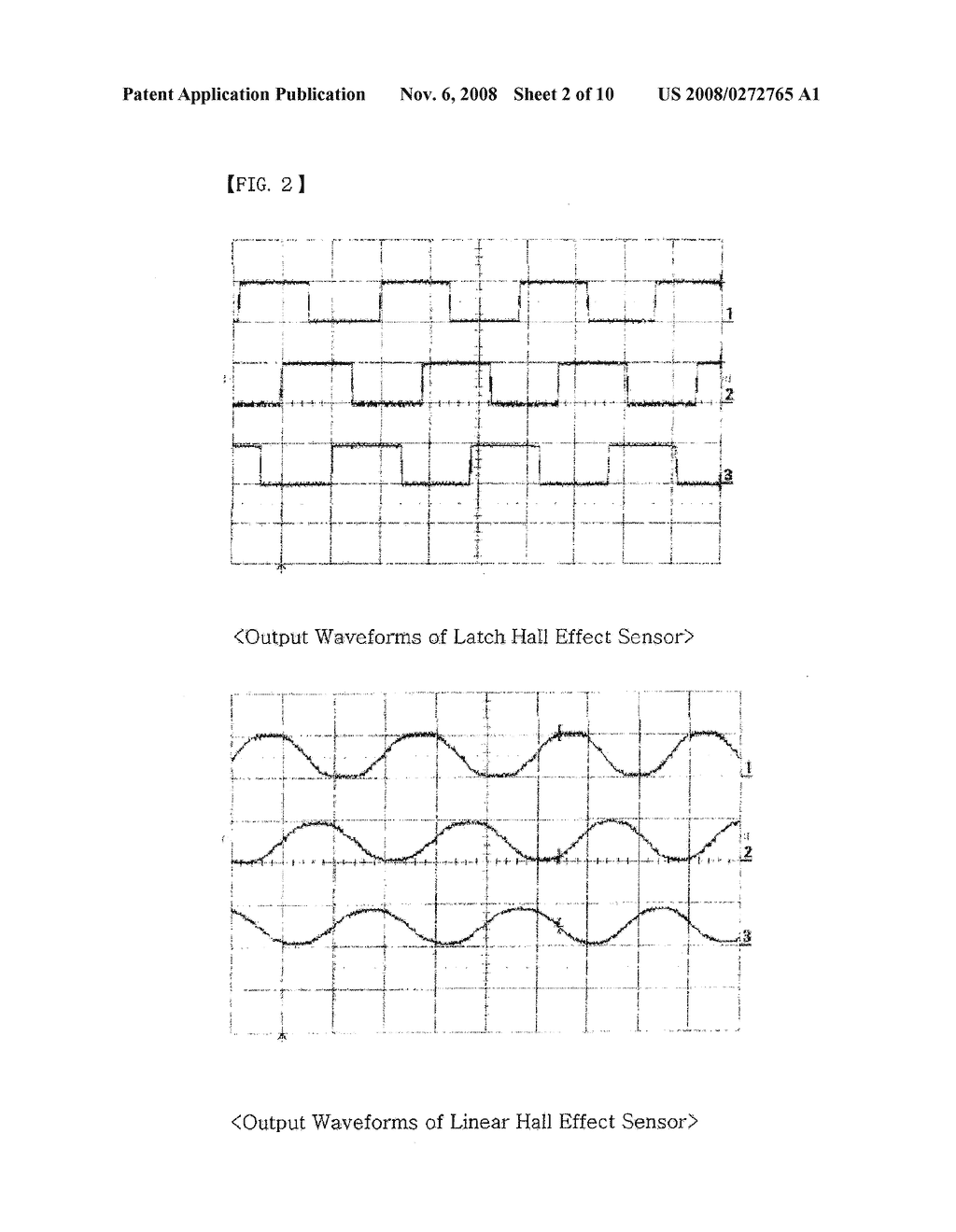
No, the issue I was fearing was that noise glitches were getting on the signal wires (they act as antennae) and those glitches were being interpreted as valid signals by the controller. The top drawing ('scope trace) shows what the waveforms from the three Hx signals should look like while the motor is in motion (moving continuously in ONE direction):
http://www.patentsencyclopedia.com/img/20080272765_03.png
You can imagine how the waveforms would look if the motor was rotating in the opposite direction!
Now, imagine you're at the point, in time, represented by the end of the second division (by way of reference, there are 10 divisions in the drawing). Signal 1 is low, signal 2 is high and signal 3 is just getting ready to transition from low to high (1,2 and 3 are equivalent to A, B and C in your schematic). What happens if a noise glitch appeared on signal 1 so that it looks to be high, again (at the instant of the glitch, you don't know that its; a glitch, yet, cuz you can't see into the future and don't know how long the signal will STAY high). That could suggest to the controller that the motor had slipped BACKWARDS... to a point in time more like the 1.5 division. What should the controller do AT THAT INSTANT? (remember, you're a bipedal hominid tottering precariously on a two wheeled device
To further confuse (the controller), imagine signal 3 had already started up to it's high level. Now, we have a situation more like division 0.5 -- the motor has apparently slipped backwards a long ways!
[All just speculation as your problem seems to happen while the motor isn't in motion at all! And, noise seems less likely given the filtering on the signals]
This is why I'd like to know what the actual signal levels are...
- Scout
- Posts: 71
- Joined: 23 Nov 2017, 21:29
- Location: USA
Re: anouther strange question on brushless motor sensors
![]() by wilsonintexas » 19 Feb 2018, 01:56
by wilsonintexas » 19 Feb 2018, 01:56
I appreciate the time you are taking on this, and appreciate that you know what you are talking about, I will try to hit some of you questions.
I would love to get them, but do not have a scope with me right now. Maybe in a few months when I get back to Dallas, and have a change to pick one up from my dad.
But I am not sure what shape they are in. They have been in a back room for years, not sure if they have the leads, or what features they have
Scout wrote:wilsonintexas wrote:I posted the question on a forum dedicated to segways and somethere posted this schematic for me.
<frown> I can't read many of the values on the schematic (hint: JPG is a bad format for line drawings -- like schematics -- because it is lossy and loses detail).
But, just looking at the general signal flow, it looks llike they took some precautions to filter out "noise" on the signal lines. E.g., R43 and C39 form a filter for the HA signal from Motor1 (there are similar caps and resistors for the other signals). The input to U71 has hysteresis to accommodate the "slowed down" filtered signal (I can't read the device type off the schematic, nor any of the values other than the 240's and 2K2's). R49 (and its equivalent R's for the other signals) "holds up" the output from the HA signal (i.e., the HA device can only pull the output DOWN, not up -- that's what R49 is there to do). At 2K2, it is a low enough impedance that I would imagine the signal to be relatively free from picking up noise that isn't already present in the "system".
So, I'd tend to discount that possibility.I checked out my wiring several times, knowing that I have had trouble concentrating. The last check was to measure the resistance by clipping a lead to the solder joint at the motor, and them checking it at a test pad for that color on the mother board...
I did have some crossed wires, that were fixed before I put the battery pack back in.
So, lets assume that's not the problem, either.I think that the startup logic stopps at he first eror, because I get an error for the same motor. AT one point, I disconnected one of the leads and it switched the error code..... and now I cannot remember which one I disconnected.
Ah, I must have missed this clue, previously (?). Does the controller throw the error as soon as you power it up? Does it make a test attempt to move the motors (perhaps just a wee bit) and THEN decide that something is wrong (because it moved the motor and didn't see the expected signal CHANGE from the sensors)?
TED sorry bad at quotes.... It throws the error at power up. I assume it does a self check....
[I'm trying to think of how I could get you to hack together a "test probe" to examine the outputs -- on the left side of the R43's -- to see if they are stuck high, low or pulsing with motor motion. What is the specific error? Or, is it so generic that it just says "Motor 1 defective"?]
TED: It would be tough to get test leads there.... The error is a series of flashing lights (3 then 9 or 3 then 6) I fond one site that groups the range as bad motor sensors. One person on the other forum mentioned which sensor it was. BUt I suspect that et stops at the first error. sometinmes when I have wires pinched it throws an eror about a foot pad sensor. .AT one point I had resoldered the leads bad put the motors back in their original configuration and everything was fine.
Meaning you had removed your "extension cords" and all was as it should be?
TED: Correct (well almost the original I had a short section of wire I let in place because the leads ere getting short.But after the last failure, I out it back and I am still getting the error code.
So, it is now failing while in the original (no extensions) configuration?
TED. correct
[Sorry, I'm not trying to pick nits -- just wanting to be sure I know which "conditions" your describing]
Ted: not a problem, I know that sometimes I can not be clear.It would have been nice to move the motors.
Why couldn't you ALSO move the segway's controller (and get rid of the segway, altogether?)
Ted: I was trying to so this with as little investment as I could. I had the Segway and I do not have another controller to put in there.
I was also trying for a quick work around,
I looked into the roboteque a little, but it costs more than I have right now, and I know that it will take a while to get it wired and working.I suspect that you are correct in that the Segway is balancing and has strict time limits. The extended leads may have been adding a time delay.
Its not a "time delay" -- electricity moves very fast (at almost the speed of light). So, adding a foot or two of wire just added a few BILLIONTHS of a second delay.
Ted: I agree..... just a brain cramp...
No, the issue I was fearing was that noise glitches were getting on the signal wires (they act as antennae) and those glitches were being interpreted as valid signals by the controller. The top drawing ('scope trace) shows what the waveforms from the three Hx signals should look like while the motor is in motion (moving continuously in ONE direction):
http://www.patentsencyclopedia.com/img/20080272765_03.png
Ted: I agree with this...
What if I ran the 3 signal leads in coax, and grounded the brading.... that may shield them.
I was also thinking that I could use the e twisted pair in the CAT 5 cable and ground all of the white leads... There are 4 pair of twisted I could run separate power and ground leads. (or do I need them shielded as well?
You can imagine how the waveforms would look if the motor was rotating in the opposite direction!
Now, imagine you're at the point, in time, represented by the end of the second division (by way of reference, there are 10 divisions in the drawing). Signal 1 is low, signal 2 is high and signal 3 is just getting ready to transition from low to high (1,2 and 3 are equivalent to A, B and C in your schematic). What happens if a noise glitch appeared on signal 1 so that it looks to be high, again (at the instant of the glitch, you don't know that its; a glitch, yet, cuz you can't see into the future and don't know how long the signal will STAY high). That could suggest to the controller that the motor had slipped BACKWARDS... to a point in time more like the 1.5 division. What should the controller do AT THAT INSTANT? (remember, you're a bipedal hominid tottering precariously on a two wheeled device
To further confuse (the controller), imagine signal 3 had already started up to it's high level. Now, we have a situation more like division 0.5 -- the motor has apparently slipped backwards a long ways!
[All just speculation as your problem seems to happen while the motor isn't in motion at all! And, noise seems less likely given the filtering on the signals]
This is why I'd like to know what the actual signal levels are...
I would love to get them, but do not have a scope with me right now. Maybe in a few months when I get back to Dallas, and have a change to pick one up from my dad.
But I am not sure what shape they are in. They have been in a back room for years, not sure if they have the leads, or what features they have
- wilsonintexas
- Posts: 140
- Joined: 26 Aug 2014, 17:51
- Location: Dallas Texas
Re: anouther strange question on brushless motor sensors
![]() by Burgerman » 19 Feb 2018, 02:07
by Burgerman » 19 Feb 2018, 02:07
Looking at that circuitry with pull up resistors etc they will be simple on/off square wave hall effect transistors x3 per motor. They dont need to be very accurate as they are geared drives. Balancing machines with normal brushed wheelchair motors work fine too...
-
Burgerman - Site Admin
- Posts: 65235
- Joined: 27 May 2008, 21:24
- Location: United Kingdom
Re: anouther strange question on brushless motor sensors
![]() by Scout » 19 Feb 2018, 05:06
by Scout » 19 Feb 2018, 05:06
[Apologies if I screw up the quotes...]
OK. When I drive a BLDC motor, the first thing I do (in the Power On Self Test) is to verify the motor is attached, the sense leads connected and it "makes sense" in its current state. Then, (depending on the nature of the mechanism to which it is attached), I rotate the motor a bit in each direction -- just to cycle through the phases and verify it seems to respond, as expected. In some applications, a motor cable might be left unplugged, or, plugged in "backwards" (so, if I drive the motor in a clockwise direction, I expect to see the feedback signals confirm this direction of rotation).
I suspect the Segway is designed with the "no user serviceable parts inside" mentality so they are expecting only "authorized dealers" to be servicing it. OTOH, they may be paranoid enough to plan for the hobbyist tinkerer (easier to perform an extra test in software than to risk a lawsuit if a tinkerer climbs on and gets thrown because the motor wiring was backwards -- because he screwed with it!).
One thing, for sure, is you can look at the three sensor signals and erify that they represent one of the six possible states: {101, 100, 110, 010, 001, 011}. In particular, 000 and 111 are "not possible". So, if the controller sees one of these two conditions, it knows that something is wrong. (1 being ~5V and 0 being ~0V)
In the 000 case, it could be that R81 has "opened" and isn't sourcing power to the three "pull up" resistors (R49, R50, R51). I can't tell if R81 is supposed to be a "0 ohm jumper" (i.e., a piece of wire) or a relatively low resistance to limit the power going off board from the onboard power supply. Assuming it is a resistor and wasn't designed to tolerate a prolonged short on its load (pin 2 of the connector), it could have simply opened from excessive power dissipation. This could occur if you had pin 2 grounded for some reason.
Even if R81 is intact, if pin 2 is presently grounded, then you'll also see 000.
If pin 2 (or the wire connecting it to the motor/sensor assembly) is open, you'll see 111. You'll also see this if pin 1 is open or if L4 truly is a wire inductor and is open.
You'll also see 111 if one or more of the hall effect sensors has been fried (i.e., because you shorted a power line -- even the 5V -- directly to any of pins 3, 4 or 5. Or, if the cable is unplugged!!
[Note, I'm not being pedantic in my logic, just trying to imagine the sorts of things that MIGHT have happened while you were tinkering]
If you know what a 'scope is, then you probably know what a VOM/DMM is, as well? If you have any reasonable DMM on hand (even one of the free harbor freight variety), you can use this on the DC Volts (20) scale and probe the voltages present on those signals.
With the cable plugged in (the P16 in the schematic), you should be able to access the signals at the motor or the circuit board. Ideally, you want to look at the signals while the cable is plugged in as that's what the controller is seeing. If you unplug the cable, the controller should throw an error because the 111 state will appear on those inputs. What you want to know is the signal levels when plugged in but not "in motion" (i.e., they should be static/unchanging so you don't need the "speed" that a 'scope provides to your observations).
This suggests you've got a broken wire or flakey connector (I can't see the parts so can't tell you how likely possibility each would be). Note that if you've plugged and unplugged the cable(s), you may have mangled/bent a pin/contact in a connector and may not see it -- unless you have evidence that it is mangled (because you see bogus values on the signal leads!) Or, may have fatigued a wire at the point it enters a connector shell and can't see the break because its inside the insulation.
Yes, but my point was that the Segway has a controller inside it (somewhere). The motors ON THE SEGWAY were wired to that controller. You tried to lengthen the wires so that you could "remote" the motors (and sensors). Could you, instead, have removed the controller from the Segway and sited it on your chair, as well? Or, is it not easily accessible IN/ON the Segway?
[And, remind me again as to the reason for your choice of the Segway... is it because it has a higher top speed than most powerchairs (for that Horse that you claim is a dog ) Or, is it just "what you happened to have on hand"?]
My initial suspicion was rooted in not having any information about the circuit and signals in question. But, the component values in the schematic you've presented suggest that "noise" won't be a problem.
A DMM would be more than adequate. You just want it to be relatively high impedance -- not "a light bulb and a piece of wire" (i.e., if the light illuminates, you have voltage present -- this is how you troubleshoot old pinball games without the fuss of a fancy meter! )
Ideally, if you could get a probe on each signal (one at a time) and note its level with the cable connected AND with the cable removed. Removed, you should see 5V on each of the 3 signals (pins 3 4 and 5). Connected, you should see 5V on no more than two signals (but AT LEAST one!) and 0v on no more than two signals (but, also, at least one!) I'm guessing this isn't the case and the controller is just throwing up its virtual hands in despair...
[You're in Calif presently? I'm sure if I look upthread I could answer this for myself based on your earlier comments re: daughter (?)]
wilsonintexas wrote:sorry bad at quotes.... It throws the error at power up. I assume it does a self check....
OK. When I drive a BLDC motor, the first thing I do (in the Power On Self Test) is to verify the motor is attached, the sense leads connected and it "makes sense" in its current state. Then, (depending on the nature of the mechanism to which it is attached), I rotate the motor a bit in each direction -- just to cycle through the phases and verify it seems to respond, as expected. In some applications, a motor cable might be left unplugged, or, plugged in "backwards" (so, if I drive the motor in a clockwise direction, I expect to see the feedback signals confirm this direction of rotation).
I suspect the Segway is designed with the "no user serviceable parts inside" mentality so they are expecting only "authorized dealers" to be servicing it. OTOH, they may be paranoid enough to plan for the hobbyist tinkerer (easier to perform an extra test in software than to risk a lawsuit if a tinkerer climbs on and gets thrown because the motor wiring was backwards -- because he screwed with it!).
One thing, for sure, is you can look at the three sensor signals and erify that they represent one of the six possible states: {101, 100, 110, 010, 001, 011}. In particular, 000 and 111 are "not possible". So, if the controller sees one of these two conditions, it knows that something is wrong. (1 being ~5V and 0 being ~0V)
In the 000 case, it could be that R81 has "opened" and isn't sourcing power to the three "pull up" resistors (R49, R50, R51). I can't tell if R81 is supposed to be a "0 ohm jumper" (i.e., a piece of wire) or a relatively low resistance to limit the power going off board from the onboard power supply. Assuming it is a resistor and wasn't designed to tolerate a prolonged short on its load (pin 2 of the connector), it could have simply opened from excessive power dissipation. This could occur if you had pin 2 grounded for some reason.
Even if R81 is intact, if pin 2 is presently grounded, then you'll also see 000.
If pin 2 (or the wire connecting it to the motor/sensor assembly) is open, you'll see 111. You'll also see this if pin 1 is open or if L4 truly is a wire inductor and is open.
You'll also see 111 if one or more of the hall effect sensors has been fried (i.e., because you shorted a power line -- even the 5V -- directly to any of pins 3, 4 or 5. Or, if the cable is unplugged!!
[Note, I'm not being pedantic in my logic, just trying to imagine the sorts of things that MIGHT have happened while you were tinkering]
[I'm trying to think of how I could get you to hack together a "test probe" to examine the outputs -- on the left side of the R43's -- to see if they are stuck high, low or pulsing with motor motion. What is the specific error? Or, is it so generic that it just says "Motor 1 defective"?]
TED: It would be tough to get test leads there.... The error is a series of flashing lights (3 then 9 or 3 then 6) I fond one site that groups the range as bad motor sensors. One person on the other forum mentioned which sensor it was. BUt I suspect that et stops at the first error. sometinmes when I have wires pinched it throws an eror about a foot pad sensor.
If you know what a 'scope is, then you probably know what a VOM/DMM is, as well? If you have any reasonable DMM on hand (even one of the free harbor freight variety), you can use this on the DC Volts (20) scale and probe the voltages present on those signals.
With the cable plugged in (the P16 in the schematic), you should be able to access the signals at the motor or the circuit board. Ideally, you want to look at the signals while the cable is plugged in as that's what the controller is seeing. If you unplug the cable, the controller should throw an error because the 111 state will appear on those inputs. What you want to know is the signal levels when plugged in but not "in motion" (i.e., they should be static/unchanging so you don't need the "speed" that a 'scope provides to your observations).
AT one point I had resoldered the leads bad put the motors back in their original configuration and everything was fine.
Meaning you had removed your "extension cords" and all was as it should be?
TED: Correct (well almost the original I had a short section of wire I let in place because the leads ere getting short.But after the last failure, I out it back and I am still getting the error code.
So, it is now failing while in the original (no extensions) configuration?
TED. correct
This suggests you've got a broken wire or flakey connector (I can't see the parts so can't tell you how likely possibility each would be). Note that if you've plugged and unplugged the cable(s), you may have mangled/bent a pin/contact in a connector and may not see it -- unless you have evidence that it is mangled (because you see bogus values on the signal leads!) Or, may have fatigued a wire at the point it enters a connector shell and can't see the break because its inside the insulation.
It would have been nice to move the motors.
Why couldn't you ALSO move the segway's controller (and get rid of the segway, altogether?)
Ted: I was trying to so this with as little investment as I could. I had the Segway and I do not have another controller to put in there.
Yes, but my point was that the Segway has a controller inside it (somewhere). The motors ON THE SEGWAY were wired to that controller. You tried to lengthen the wires so that you could "remote" the motors (and sensors). Could you, instead, have removed the controller from the Segway and sited it on your chair, as well? Or, is it not easily accessible IN/ON the Segway?
[And, remind me again as to the reason for your choice of the Segway... is it because it has a higher top speed than most powerchairs (for that Horse that you claim is a dog
No, the issue I was fearing was that noise glitches were getting on the signal wires (they act as antennae) and those glitches were being interpreted as valid signals by the controller. The top drawing ('scope trace) shows what the waveforms from the three Hx signals should look like while the motor is in motion (moving continuously in ONE direction):
http://www.patentsencyclopedia.com/img/20080272765_03.png
Ted: I agree with this...
What if I ran the 3 signal leads in coax, and grounded the brading.... that may shield them.
My initial suspicion was rooted in not having any information about the circuit and signals in question. But, the component values in the schematic you've presented suggest that "noise" won't be a problem.
I would love to get them, but do not have a scope with me right now. Maybe in a few months when I get back to Dallas, and have a change to pick one up from my dad.
But I am not sure what shape they are in. They have been in a back room for years, not sure if they have the leads, or what features they have
A DMM would be more than adequate. You just want it to be relatively high impedance -- not "a light bulb and a piece of wire" (i.e., if the light illuminates, you have voltage present -- this is how you troubleshoot old pinball games without the fuss of a fancy meter!
Ideally, if you could get a probe on each signal (one at a time) and note its level with the cable connected AND with the cable removed. Removed, you should see 5V on each of the 3 signals (pins 3 4 and 5). Connected, you should see 5V on no more than two signals (but AT LEAST one!) and 0v on no more than two signals (but, also, at least one!) I'm guessing this isn't the case and the controller is just throwing up its virtual hands in despair...
[You're in Calif presently? I'm sure if I look upthread I could answer this for myself based on your earlier comments re: daughter (?)]
- Scout
- Posts: 71
- Joined: 23 Nov 2017, 21:29
- Location: USA
Re: anouther strange question on brushless motor sensors
![]() by Burgerman » 19 Feb 2018, 07:16
by Burgerman » 19 Feb 2018, 07:16
Looking at that circuitry with pull up resistors etc they will be simple on/off square wave hall effect transistors x3 per motor. They dont need to be very accurate as they are geared drives. Balancing machines with normal brushed wheelchair motors work fine too...
And even if they are linear hall affect ones, so you just get 3 sine waves, lengthening the wires a sensible amount should also cause no problems. Unless you wired it wrong and fried something...
-
Burgerman - Site Admin
- Posts: 65235
- Joined: 27 May 2008, 21:24
- Location: United Kingdom
Re: anouther strange question on brushless motor sensors
![]() by wilsonintexas » 20 Feb 2018, 00:39
by wilsonintexas » 20 Feb 2018, 00:39
Thanks for the comments.
They are brushless motors.
I am going to put the leads back to the original length and double check that I did not cross the wires and redo the solder connections today.
I added in about 5 feet of additional wires to get the leads down the chair and across to the motor. I could have broken a wore or pulled a lead on the motor with as much handling I have done getting them in and out for testing.
I have some new motors coming jut in case.
Again thanks for your time on this. I will let you know how it goes.
I may be able to do more testing and get a scope on it in a few months, but if I get it working as a mule I will let it be for now. I hope to be headed back to Dallas within a month or so.....
- wilsonintexas
- Posts: 140
- Joined: 26 Aug 2014, 17:51
- Location: Dallas Texas
Re: anouther strange question on brushless motor sensors
![]() by wilsonintexas » 20 Feb 2018, 02:32
by wilsonintexas » 20 Feb 2018, 02:32
One last update:
I redid the leads (more to ensure that all of the solder joints were good, and to put on the correct heat shrink. (I had run out of it during he last trial)
I am kicking myself, I had it working by taking it back to the original configuration, but then tried to extend the leads again, thinking I had just crossed the wires. Back to Error code.
So I took it back to original config, and I still have the error code. (39)
I then swapped the motors around, and the error code went to 36.
So It looks like it is a problem with the first sensor that is now motor 1. I assume that it is hall a on the current left motor (based on the diagram above.
I have a pair of new motors coming, that I won on ebay. After I get it working, I may take the motor apart ans see if I can trace down the problem.
- wilsonintexas
- Posts: 140
- Joined: 26 Aug 2014, 17:51
- Location: Dallas Texas
Re: anouther strange question on brushless motor sensors
![]() by Scout » 21 Feb 2018, 03:16
by Scout » 21 Feb 2018, 03:16
wilsonintexas wrote:So I took it back to original config, and I still have the error code. (39)
I then swapped the motors around, and the error code went to 36.
A quick google shows 36-41 as "motor error codes" (perhaps I can find more detail if I spent more time on it).
I'll assume 36, 37, and 38 pertain to one motor (e.g., the "left" motor) and 39, 40, 41 pertain to the other motor ("right"). The fact that there are three codes for each motor doesn't mean that they correspond to the three hall effect sensors (36/39 might mean "funky hall effect signal detected"; 37/40 might mean "open motor winding detected" and 38/41 might mean "shorted motor winding detected" -- or, something else entirely!)
But, it does appear that the problem is following the actual motor. This suggests that the problem is on/in the motor OR the harness that connects the motor to the board. E.g., a bad connector on motor 1's pigtail could manifest as a fault that "moves" based on where you have it plugged in. (or, it could be something internal to the motor that appears to shift when you swap the motor with its mate)
- Scout
- Posts: 71
- Joined: 23 Nov 2017, 21:29
- Location: USA
Re: anouther strange question on brushless motor sensors
![]() by wilsonintexas » 25 Feb 2018, 22:15
by wilsonintexas » 25 Feb 2018, 22:15
I missed one of your earlier posts, I will try to answer some of the questions.
I do have a volt meter, and will try to get some readings, the next time I get the motors wired for the remote location.
You asked why a Segway...... because I picked one up pretty cheep.....
why not remount the controller. or the whole thing on the chair ...... space... The controller is mounted in the base of the Segway and has some built in gyro sensors that control forward and back. and a tilt arm that controls right and left.
To get all of that extended so I can control it is difficult.
When I get the new motor is, I will try to test the old one and see where the problem with the sensor is. If is is just a broken lead, then I may try to extend them again....
I think I will try extending the leads on just one motor at a time..... it will save time... I will also add in an extra lead so I can take voltage readings on each sensor. . If I can extend one, I will do both of them.
If I get a sensor failure, I will get the volt readings and see
I have a replacement motor coming, and for now I ill get it working as a mule......
I am running out of time to fool with it. I hope to be on the road back to Texas, and need it to exercise the dog on the trip.
right now I take him for runs alongside an ATV, and I will not be taking that with me.
- wilsonintexas
- Posts: 140
- Joined: 26 Aug 2014, 17:51
- Location: Dallas Texas
Re: anouther strange question on brushless motor sensors
![]() by wilsonintexas » 27 Feb 2018, 04:47
by wilsonintexas » 27 Feb 2018, 04:47
Frustrating day.
Had snow mixed with freezing rain. At about 5 inches I decided to plow. I knew if it froze solid it would be a real pain to clear.
I clear 5 houses on my street, just to be a good neighbor. This was on top of another 5 inches late last week. Some of the edges of the drives were getting pretty deep, so I spent the time to pull a lot of it into the drive and then out into the street. Of course I then needed to plow the street; I could not leave it blocked. We live on a side street and it would be 4 or 5 days before they plow it.
After 3 hours, I ended up with my beaver skin hat covered in snow that dripped down my neck, (but my head was arm). I had water logged winter overalls, gloves and very cold hands.
It is still spitting it down and there is another 3 inches on top of what I cleared. That will have to wait until tomorrow.
After I sat in the hot tub to thaw out, the mail man rang the bell, to let me know a package was sitting out in the freezing rain.
The new motors came. And I swapped them out. I then ran into a new problem. There are 2 foot sensors, and one of them had been giving me a fit, but if I thumped it would clear….. Not any longer. This is a finicky machine. So I swapped them over, and the error code switched sides.
I ended up taking the sensor lead from the bad side, and patching it into the lead from the good side…. IT worked….
So just put the tire on the new motor, and on to the next test…. (I was going to try a lead extension, knowing that I now had 2 spare motors…..)
I could not get the new tire to seat….. Looked for the valve stem puller…… nowhere to be found. I KNO I bought 4 of them on valve caps, and put them on the RV and car……. But that must be me just wishing I had….. I had been trying a smaller compressor that is in the warm heated garage….
Tried a strap around the tire to try and get it to grab….. That worked last time…
So out to the still snowing/ freezing rain (I just checked the air temp is 28) and fire up the big compressor in the RV….. Drop the adapter for the inflator in the snow…. Twice…. And still could not get it to seat.
Tried the strap. No luck….
Back inside and soak the hands in the hot tub for a few minutes…..
So…. Tomorrow I go up the road to a local garage, and see if they can seat it for me… I bet they have a valve stem puller.
After I get it working, I will try the lead extension and see how it goes. If it does not work, I will get it back up as a mule.
Then to really finish the day, we are in the tail end of a Geomagnetic storm, and the Aurora should be good….. but it is cloudy. I have set up the RV to mount the camera on the TV antenna, and have the computer set up for time lapse. This year the weather has not cooperated.
I have an album on IMGUR with a lot of the animated GIFS from the past two years… If it is ok, I will start a new thread and post a link…. But it is way off topic.
I have a mail list that I send an email out to with the link when I get a new set of shots… if anyone is interested, drop me a PM and I will add you to the list.
So I hope that all of you are having a better day than I did.
- wilsonintexas
- Posts: 140
- Joined: 26 Aug 2014, 17:51
- Location: Dallas Texas
16 posts
• Page 1 of 1
Return to Everything Powerchair
Who is online
Users browsing this forum: No registered users and 87 guests