
![]() by Scooterman » 16 Feb 2019, 13:12
by Scooterman » 16 Feb 2019, 13:12

![]() by Burgerman » 16 Feb 2019, 13:48
by Burgerman » 16 Feb 2019, 13:48

![]() by LROBBINS » 16 Feb 2019, 15:34
by LROBBINS » 16 Feb 2019, 15:34
![]() by Burgerman » 16 Feb 2019, 15:53
by Burgerman » 16 Feb 2019, 15:53
![]() by Scooterman » 16 Feb 2019, 16:14
by Scooterman » 16 Feb 2019, 16:14
![]() by Scooterman » 16 Feb 2019, 16:20
by Scooterman » 16 Feb 2019, 16:20
![]() by Burgerman » 16 Feb 2019, 16:21
by Burgerman » 16 Feb 2019, 16:21
![]() by LROBBINS » 16 Feb 2019, 18:31
by LROBBINS » 16 Feb 2019, 18:31
![]() by ex-Gooserider » 26 Feb 2019, 05:57
by ex-Gooserider » 26 Feb 2019, 05:57

![]() by Scooterman » 27 Feb 2019, 08:39
by Scooterman » 27 Feb 2019, 08:39
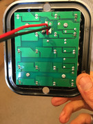
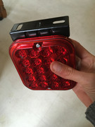
ex-Gooserider wrote:If you have a variable voltage supply (a Shirley supply works great for this) try hooking up and turning on at zero volts. Slowly increase the voltage and see what voltage the LED's start turning on at... You will probably just start seeing them light up around 7-8V.
Then note how bright they are at about 13-14V (the actual voltage put out by a '12V' car battery) and see if they get significantly brighter as you increase to 24V... (or really 26-28V)
If they do, then back down the voltage, if they don't, then feel around on the circuit board (especially any non-LED components) and see if anything is getting warm after a few minutes.... If any part is more than warm, I'd worry about operating at 24V
There may be a current limiter as Lenny said, or it may be a case of the LED's being wired with parts that let them work optimally at 12V and not blow at 24V, but be 'stressed'....
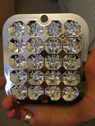
LED's need to be wired with a 'current limiting resistor' to keep the amount of current flowing through them at the appropriate value which is chosen to give as much light as possible while lasting the manufacturer specified life... The value of the resistor is calculated based on the diode specs and the intended operating voltage... For any given resistor, at some voltage they will start putting out light which will gradually get brighter as the voltage increases - and they will keep getting brighter until they blow.... If you set the voltage at something above 'optimum' for that resistor, but less than the 'blow' value, the LED will work and be very bright, but have a much shorter life than it should... If the voltage is less, you won't get as much light, but the LED will just about last forever...
If I was trying to make a 'dual voltage' light, I might pick a resistor value that is 'optimal' for around 18V knowing that I'd get an OK amount of light at 12V, and be stressed but last long enough to have the warranty expire before crapping out at 24V....
I tend to be on the conservative side about this, especially in something safety critical like a tail light, so unless I either had explicit promises (and could see signs of designing to do it) about dual voltage, or saw no signs of 'stress' at 24V, I would either stick with running at 12V or add an additional resistor as mentioned earlier...
ex-Gooserider
![]() by shirley_hkg » 27 Feb 2019, 09:19
by shirley_hkg » 27 Feb 2019, 09:19
![]() by Burgerman » 27 Feb 2019, 09:21
by Burgerman » 27 Feb 2019, 09:21
![]() by Scooterman » 28 Feb 2019, 09:19
by Scooterman » 28 Feb 2019, 09:19
shirley_hkg wrote:Solid State contactors . No sparks !
Do you want one or two ?
Burgerman wrote:AC ones wont work. But the above can be DC/DC too.
OR big and overkill https://www.ebay.co.uk/itm/SSR-25-DD-DC ... rk:34:pf:0
Will run powerful headlamps or an actuator...
Solid state.
![]() by Burgerman » 28 Feb 2019, 12:18
by Burgerman » 28 Feb 2019, 12:18
![]() by Scooterman » 28 Feb 2019, 12:28
by Scooterman » 28 Feb 2019, 12:28
![]() by Scooterman » 28 Feb 2019, 16:09
by Scooterman » 28 Feb 2019, 16:09
Return to Everything Powerchair
Users browsing this forum: DrewDigital and 120 guests