China Aircraft Lithium Battery (company). Originally.
I think, from memory. A known brand that makes cells you can rely on being what they claim to be.
LiFePo4 for Permobil C500S
Re: LiFePo4 for Permobil C500S
![]() by Burgerman » 10 Mar 2019, 20:39
by Burgerman » 10 Mar 2019, 20:39
-

Burgerman - Site Admin
- Posts: 65429
- Joined: 27 May 2008, 21:24
- Location: United Kingdom
Re: LiFePo4 for Permobil C500S
![]() by quadcopter » 10 Mar 2019, 22:07
by quadcopter » 10 Mar 2019, 22:07
I didn't find any mention about CALB on the battery pages:
https://winston-battery.en.made-in-china.com/product/ECZQljfFfWhH/China-105ah-LiFePO4-Battery-Lithium-Iron-Phosphate.html
https://www.alibaba.com/product-detail/Long-cycle-life-Rechargeable-lifepo4-battery_60787932515.html?spm=a2700.icbuShop.82.5.49843f51YmB5UC
How do you know that it's CALB?
https://winston-battery.en.made-in-china.com/product/ECZQljfFfWhH/China-105ah-LiFePO4-Battery-Lithium-Iron-Phosphate.html
https://www.alibaba.com/product-detail/Long-cycle-life-Rechargeable-lifepo4-battery_60787932515.html?spm=a2700.icbuShop.82.5.49843f51YmB5UC
How do you know that it's CALB?
- quadcopter
- Posts: 116
- Joined: 04 Jul 2016, 21:32
Re: LiFePo4 for Permobil C500S
![]() by expresso » 10 Mar 2019, 22:48
by expresso » 10 Mar 2019, 22:48
I would just take 10ah off the top - of any of these Cells - for a few reasons - but most important - is they have a 100ah Cell - but to get 100ah out of it - you have to discharge down to 2v and or 2.5V they will say. in our case - we dont go that low and will get about 10ah less overall
this is just my opinion and from asking the sellers also - i was told that 100ah Cell may get about 92ah to 96ah - if down to 2.9V - at least if you get 90ah - its still fine - so what ever Cell you find - take 10ah off the top to have an idea - it Can be Better - but shouldnt be less than 10ah unusable to us.
this is what i been noticing - others may have better results - or find better Cells etc, - its hit and miss - but i woulnd worry if any cells we get give out a bit less than stated - unless its alot less - would be great if only 5ah less -
which i got a 60ah Cell that way - get a good solid 55ah out of them - i did get one weak cell which i got replaced - - next batch of 80ah cells - get about 70ah out of them at 2.9v - - i still refer to them as 60ah and 80ah to keep it less confusing what i got.
and i never replaced the weak cell yet - because its working fine and getting more than enough out of for that chair - one day i will take it apart and replace it - but as long as i keep the pack safe at 2.9v for the weakest cell - i still managed 36 miles
Quickie 636 - 230ah LifePo4
- expresso
- Posts: 11919
- Joined: 10 May 2010, 03:17
Re: LiFePo4 for Permobil C500S
![]() by Burgerman » 10 Mar 2019, 23:07
by Burgerman » 10 Mar 2019, 23:07
Was just going by the calb page here, they are the only ones I ever saw with a copper and an alloy terminal on each.
http://www.evlithium.com/CALB_Battery/224.html
Winston, sinoply, calb, headway, A123, and others are all good. Known brands that ship vast quantities.
http://www.evlithium.com/lifepo4-battery-news/428.html
But there are thousands of unbranded and unknown quantity cells sold from china, ebay etc. They may be one of the big brands but out of the back door. Or sold legitimately to 3rd party vendors. They may be perfectly good and manufacturered by small businesses that nobody heard of. Or they may be cells that rejected in tests, but new by the big manufacturers and sold to 3rd party vendors. Or cells taken out of service in huge quantities and replaced with new. Why does that happen? A bad cell, a stupid BMS and any number of reasons can leave a pack with groups of cells that have failed. Takes time to sort the good from the bad so they get sold off cheap and replaced the lot in one go. The problem is knowing what you are buying as they all use the best and same pictures and specs.
It pays if you have time to get a sample, and test under load to measure resistance, and to test capacity. And test for a reasonable self discharge level. But even then you dont know that thats what you will actually get. So going for any known genuine battery, or cell from a high volume supplier is wise.
-
Burgerman - Site Admin
- Posts: 65429
- Joined: 27 May 2008, 21:24
- Location: United Kingdom
Re: LiFePo4 for Permobil C500S
![]() by quadcopter » 10 Mar 2019, 23:27
by quadcopter » 10 Mar 2019, 23:27
Ok, batteries, charger (Revolectrix PL8).
What else do I need?
I looked at swalker's Build Parts List and there are a lot of things.
Are there any manual/scheme/photos with step-by-step explain?
What else do I need?
I looked at swalker's Build Parts List and there are a lot of things.
Are there any manual/scheme/photos with step-by-step explain?
- quadcopter
- Posts: 116
- Joined: 04 Jul 2016, 21:32
Re: LiFePo4 for Permobil C500S
![]() by quadcopter » 10 Mar 2019, 23:31
by quadcopter » 10 Mar 2019, 23:31
- quadcopter
- Posts: 116
- Joined: 04 Jul 2016, 21:32
Re: LiFePo4 for Permobil C500S
![]() by quadcopter » 10 Mar 2019, 23:38
by quadcopter » 10 Mar 2019, 23:38
Many LiFePo4 cells have width 173 mm. Looks like it's purpose to fit Group 24 (it has width 173).
Am I correct?
I'll measure my wheelchair battery cases later.
Am I correct?
I'll measure my wheelchair battery cases later.
- quadcopter
- Posts: 116
- Joined: 04 Jul 2016, 21:32
Re: LiFePo4 for Permobil C500S
![]() by Burgerman » 10 Mar 2019, 23:45
by Burgerman » 10 Mar 2019, 23:45
No its just luck... MK is 168mm. But some GRP24 can be up to 173. But they wont fit in some chairs. E.G. my Invacare storm 4 explore. Thats an exact fit to MKs... They will go in my Salsa, and its bigger than 173 because you need insulation at all 4 edges and between cells.
-
Burgerman - Site Admin
- Posts: 65429
- Joined: 27 May 2008, 21:24
- Location: United Kingdom
Re: LiFePo4 for Permobil C500S
![]() by swalker » 11 Mar 2019, 01:19
by swalker » 11 Mar 2019, 01:19
Burgerman wrote:No its just luck... MK is 168mm. But some GRP24 can be up to 173..
The spec sheet for the MK M24 SLD G FT group 24 gel batteries I use in my two Permobil C500 wheelchairs as well as (currently) in my Magic Mobility X4 says they are 173 mm wide. I have measured mine and they do measure at 173mm.
Steve
- Attachments
-
- MK M24 SLD G FT spec sheet
Permobil F5 Corpus 3G
Permobil C500s VS
Permobil C500 Corpus 3G
Permobil C350 Corpus 3G
Magic Mobility X4 with 176 Ah LiFePO4
Permobil C500s VS
Permobil C500 Corpus 3G
Permobil C350 Corpus 3G
Magic Mobility X4 with 176 Ah LiFePO4
- swalker
- Posts: 550
- Joined: 23 Jul 2018, 22:57
- Location: Vail, Colorado, USA
Re: LiFePo4 for Permobil C500S
![]() by jefferso » 11 Mar 2019, 01:26
by jefferso » 11 Mar 2019, 01:26
What will the weight difference be between MK Lead batteries and a lithium pack? It will change the centre of gravity in a Permobil C500 some but will it have a noticeable effect on stability? I've never tipped to the side in mine, but I've been on some slopes that made me feel like I could.
- jefferso
- Posts: 171
- Joined: 18 Jun 2016, 22:18
Re: LiFePo4 for Permobil C500S
![]() by Burgerman » 11 Mar 2019, 01:38
by Burgerman » 11 Mar 2019, 01:38
My bad I thought they were the same width as the GRP34. Since a 34 and 24 grp batteries are the same basic external limits, but 1 inch shorter.
GRP 34 10.20 (259) 6.65 (169) 7.05 (179)
Well it depends how many Ah you replaced the grp 24s with. Its usually about half (120Ah) to just under 2/3rds if you can actually get 180Ah in there. Is stability affected? Yes. If you have a chair ift, or a heavy car type seat you may notice the difference as you are laid on the road. If its a concern, add a layer of lead below the battery. Where its actually more effective as its lower than the lead bricks. So you may need a little less.
GRP 34 10.20 (259) 6.65 (169) 7.05 (179)
What will the weight difference be between MK Lead batteries and a lithium pack? It will change the centre of gravity in a Permobil C500 some but will it have a noticeable effect on stability? I've never tipped to the side in mine, but I've been on some slopes that made me feel like I could.
Well it depends how many Ah you replaced the grp 24s with. Its usually about half (120Ah) to just under 2/3rds if you can actually get 180Ah in there. Is stability affected? Yes. If you have a chair ift, or a heavy car type seat you may notice the difference as you are laid on the road. If its a concern, add a layer of lead below the battery. Where its actually more effective as its lower than the lead bricks. So you may need a little less.
-
Burgerman - Site Admin
- Posts: 65429
- Joined: 27 May 2008, 21:24
- Location: United Kingdom
Re: LiFePo4 for Permobil C500S
![]() by swalker » 11 Mar 2019, 03:46
by swalker » 11 Mar 2019, 03:46
The spec sheet for the 176 Ah LiFePO4 cells I am using says that each cell weighs 3.8 kg. I have not weighed them, but they feel about that heavy.
Those are the cells I am using to build a battery pack for my Magic Mobility X4 wheelchair (which also uses group 24 batteries). If that goes well, I will build up a lithium pack for my C500s VS. Like you, I am aware that I will be reducing the ballast if I do so. On the C500, I can't see any place to add ballast to make up the difference.
There will be 4 of those cells for each MK M24 SLD G FT group 24 lead acid gel battery. The spec sheet for the MK M24 SLD G FT says they weigh 23 kg each.
So, I will replace the two lead acid batteries at 23 kg each with eight LiFePO4 cells at 3.8 kg each. In other words, 46 kg of lead acid will be replaced by 30.4 kg of LiFePO4. The LiFePO4 will be 15.6 kg lighter, which is about 34.4 pounds (for those of us still using that archaic system of measurement:)).
I have not accounted for the weight of the extra wiring, ring terminals, insulation. I imagine all of that extra stuff will add up to a pound or two (depends largely on the size of wire used).
Steve
Permobil F5 Corpus 3G
Permobil C500s VS
Permobil C500 Corpus 3G
Permobil C350 Corpus 3G
Magic Mobility X4 with 176 Ah LiFePO4
Permobil C500s VS
Permobil C500 Corpus 3G
Permobil C350 Corpus 3G
Magic Mobility X4 with 176 Ah LiFePO4
- swalker
- Posts: 550
- Joined: 23 Jul 2018, 22:57
- Location: Vail, Colorado, USA
Re: LiFePo4 for Permobil C500S
![]() by quadcopter » 12 Mar 2019, 11:01
by quadcopter » 12 Mar 2019, 11:01
There is Revolectrix GT1200 Charger http://www.revolectrix.com/GT1200_description_tab.htm.
It looks like Revolectrix Cellpro PowerLab 8. Specs are very similar. But price is twice less.
Who know what's the difference?
It looks like Revolectrix Cellpro PowerLab 8. Specs are very similar. But price is twice less.
Who know what's the difference?
- quadcopter
- Posts: 116
- Joined: 04 Jul 2016, 21:32
Re: LiFePo4 for Permobil C500S
![]() by Burgerman » 12 Mar 2019, 11:22
by Burgerman » 12 Mar 2019, 11:22
Its a non PC software cut down budget version for the typical hobby flyer on a feild.
It has half the options, less power, less discharge power, more importantly less balance power, and it has no CCS software which is pretty much essential. Its algo for LiFePO4 isnt suitable and will give error messages if one cell is more than 150mV higher than the rest, and its all safety nazid up with error messages to trip you up that I cant remove or adjust. You are stuck with the presets and restrictions it comes with. The PL8 firmware was modded (fixed) to suit large LiFePO4 non hobby packs, after I was in discussions and at times arguments for 2 years with the beta testing group and I did a lot of testing of firmware to find the issues. Same with lead. And I mod the presets to take advntage of these changes in a way that isnt visible anywhere officially. So it can PROPERLY charge LiFePO4 as well as lead. Non of the rest of their range or any of the other high end chargers can do that correctly.
It has half the options, less power, less discharge power, more importantly less balance power, and it has no CCS software which is pretty much essential. Its algo for LiFePO4 isnt suitable and will give error messages if one cell is more than 150mV higher than the rest, and its all safety nazid up with error messages to trip you up that I cant remove or adjust. You are stuck with the presets and restrictions it comes with. The PL8 firmware was modded (fixed) to suit large LiFePO4 non hobby packs, after I was in discussions and at times arguments for 2 years with the beta testing group and I did a lot of testing of firmware to find the issues. Same with lead. And I mod the presets to take advntage of these changes in a way that isnt visible anywhere officially. So it can PROPERLY charge LiFePO4 as well as lead. Non of the rest of their range or any of the other high end chargers can do that correctly.
-
Burgerman - Site Admin
- Posts: 65429
- Joined: 27 May 2008, 21:24
- Location: United Kingdom
Re: LiFePo4 for Permobil C500S
![]() by quadcopter » 12 Mar 2019, 14:12
by quadcopter » 12 Mar 2019, 14:12
So it's the list what I need to build wheelchair pack (please correct/add me):
1. 8 LiFePo4 cells.
2. Connectors for cells. To connect separate cells in pack.
3. JST-XH 8S Connector (from every cells to charger).
4. Cellpro (JST PA) PowerLab 36" Extension Cable (from JST connector to charger).
http://www.usastore.revolectrix.com/Products_2/Cellpro-PowerLab-8-EC5-version_2/Cellpro-JST-PA-PowerLab-36-Extension-Cable?whence=
5. The charger - Revolectrix Cellpro PowerLab 8.
http://www.store.revolectrix.com/Products/Cellpro-PowerLab-8-EC5-version/Cellpro-PowerLab-8_2813
6. Revolectrix 24V50A PowerSupply.
http://www.store.revolectrix.com/Products/Cellpro-PowerLab-8-EC5-version/24-VDC-50A-Power-Station
7. Revolectrix FUIM3 USB Interface Module for 2-way data communication (to connect PL8 to PC).
http://www.usastore.revolectrix.com/Products_2/Cellpro-PowerLab-8-EC5-version_2/FUIM3_139?whence=
8. Cellpro PowerLab, Stackable, 40A Safety Banana Plug Cable (from charger to cells).
http://www.usastore.revolectrix.com/Products_2/Cellpro-PowerLab-8-EC5-version_2/Cellpro-PowerLab-Stackable-40A-Safety-Banana-Plug-Cable_2?whence=
1. 8 LiFePo4 cells.
- RJ 176Ah
- rj_176Ah.png (55.83 KiB) Viewed 6298 times
2. Connectors for cells. To connect separate cells in pack.
- Connector
3. JST-XH 8S Connector (from every cells to charger).
- JST-XH 8S Connector
- JST-XH 8S Connector.jpg (6.63 KiB) Viewed 6298 times
4. Cellpro (JST PA) PowerLab 36" Extension Cable (from JST connector to charger).
http://www.usastore.revolectrix.com/Products_2/Cellpro-PowerLab-8-EC5-version_2/Cellpro-JST-PA-PowerLab-36-Extension-Cable?whence=
5. The charger - Revolectrix Cellpro PowerLab 8.
http://www.store.revolectrix.com/Products/Cellpro-PowerLab-8-EC5-version/Cellpro-PowerLab-8_2813
6. Revolectrix 24V50A PowerSupply.
http://www.store.revolectrix.com/Products/Cellpro-PowerLab-8-EC5-version/24-VDC-50A-Power-Station
7. Revolectrix FUIM3 USB Interface Module for 2-way data communication (to connect PL8 to PC).
http://www.usastore.revolectrix.com/Products_2/Cellpro-PowerLab-8-EC5-version_2/FUIM3_139?whence=
8. Cellpro PowerLab, Stackable, 40A Safety Banana Plug Cable (from charger to cells).
http://www.usastore.revolectrix.com/Products_2/Cellpro-PowerLab-8-EC5-version_2/Cellpro-PowerLab-Stackable-40A-Safety-Banana-Plug-Cable_2?whence=
- quadcopter
- Posts: 116
- Joined: 04 Jul 2016, 21:32
Re: LiFePo4 for Permobil C500S
![]() by Burgerman » 12 Mar 2019, 14:21
by Burgerman » 12 Mar 2019, 14:21
You dont want download/file.php?id=10588&mode=view
Much better to use cable and ring terminals for several reasons.
The 36 inch extentions are all you need, get 4. Not the JST-XH 8S Connector
And there are many different power supplies.
dont bother with the overpriced saafe banana plugs, with cables. Those same connectors are available 10 or 20 at a time for less on eBay. Without too short wires already attached.
-
Burgerman - Site Admin
- Posts: 65429
- Joined: 27 May 2008, 21:24
- Location: United Kingdom
Re: LiFePo4 for Permobil C500S
![]() by Burgerman » 12 Mar 2019, 14:23
by Burgerman » 12 Mar 2019, 14:23
To finish the job properly you need a proper charge cable making up. With the other half on the chair.

-
Burgerman - Site Admin
- Posts: 65429
- Joined: 27 May 2008, 21:24
- Location: United Kingdom
Re: LiFePo4 for Permobil C500S
![]() by Burgerman » 12 Mar 2019, 14:27
by Burgerman » 12 Mar 2019, 14:27
-
Burgerman - Site Admin
- Posts: 65429
- Joined: 27 May 2008, 21:24
- Location: United Kingdom
Re: LiFePo4 for Permobil C500S
![]() by Burgerman » 12 Mar 2019, 14:29
by Burgerman » 12 Mar 2019, 14:29
-
Burgerman - Site Admin
- Posts: 65429
- Joined: 27 May 2008, 21:24
- Location: United Kingdom
Re: LiFePo4 for Permobil C500S
![]() by foghornleghorn » 12 Mar 2019, 15:01
by foghornleghorn » 12 Mar 2019, 15:01
Do you put a fuse in your charge cable?
-

foghornleghorn - Posts: 645
- Joined: 20 Mar 2018, 16:29
- Location: South East England
Re: LiFePo4 for Permobil C500S
![]() by swalker » 12 Mar 2019, 21:55
by swalker » 12 Mar 2019, 21:55
I need to say that I have not yet finished building up my LiFePO4 batteries. So, anything I report is preliminary.
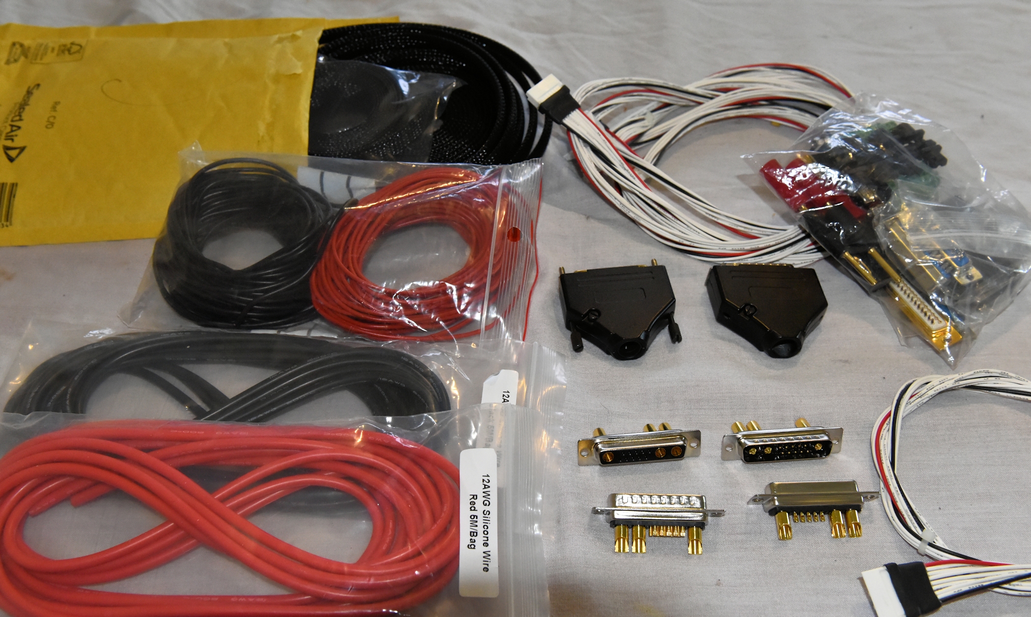
But, in getting to where I am at now, I found that figuring out wiring and connection was the part that required the most research. Here are few bits and pieces I learned along the way.
Connectors often have a gender. In what I write below, I will use the convention that the gender is determined by the metal bits, not the plastic housing. This can be a bit confusing, as various sources use the opposite convention.
In total, I used four of the Revolectrix 36" JST-PA cables. I found that was the least expensive way to buy silicone-insulated, 22 awg, tinned, copper wire. I wound up not using any of the Revolectrix JST-PA pigtails that I purchased. I would have used JST-PA connectors throughout for the ballance and cell monitor wiring, but found that the Cell Monitor required JST-XH. That is the only JST-XH connector I am using.
I wrapped all wires in wiring loom material and secured the ends with adhesive-lined, 3:1 heat shrink tubing. I also used that heat shrink tubing at all exposed connectors.
I prefer crimp connections to solder connections. Others strongly disagree with me. My reasoning is that soldering has the potential to introduce a transition between flexible wire and rigid wire, which can be prone to breaking. A properly done solder connection is less susceptible to this issue. Crimped connections have the potential to corrode, which decreases their conductivity. Corrosion is not a significant issue where I live. I only used solder connections for the dsub 13W3, which comes with cups for soldering the wires into and is enclosed in a shell that provides strain relief and prevents the wires from flexing in the vicinity of the solder joint. Everything else is crimped.
For crimping, I used crimp tools that are specifically designed for the material being crimped. I have a selection of ratcheting crimpers to choose from. I have not yet crimiped the 6 AWG wires to connect the cells and am not sure what I am going to do about those. I may solder them. An appropriate crimper is a bit expensive for those.
Steve
But, in getting to where I am at now, I found that figuring out wiring and connection was the part that required the most research. Here are few bits and pieces I learned along the way.
Connectors often have a gender. In what I write below, I will use the convention that the gender is determined by the metal bits, not the plastic housing. This can be a bit confusing, as various sources use the opposite convention.
- The Revolectrix Power Supply does not come with wires to connect to the Revolectrix PL8. The PL8 has a wire with a female EC5 connector. I bought a 10 AWG pigtail with a male EC5. I connected that pigtail's bare wires to the Revolectrix power supply and its male EC5 to the PL8's female EC5 connector.
- The PL8 accepts 4mm banana plugs for the power connections and a 9 wire female JST-PA connector for the balance lead. I used the Revolectrix safe banana plugs pigtail and 36" JST-PA cable for this.
- The cable set coming from the PL8 needs to connect to the wheelchair somewhere. Based on recommendations I found on this site, I chose to use a dsub 13W3 connector. I put the male side of the connector on the cable coming from the PL8 and the female side on the connector attached to the wheelchair. dsub 13W3 connectors are available with different power ratings. Be sure to get the 40 amp ones. My spreadsheet has the part numbers for those.
- I want to be able to disconnect the batteries from the dsub 13W3 for future maintenance needs. Therefore, I use 2 cables, one coming from the dsub 13W3 to an SB50 anderson connector (which is genderless) for the power wires and a male JST-PA connector for the ballance wires.
- The final leg of the wiring is to the batteries. That cable uses an SB50 anderson connector for the power wires and a female JST-PA connector for the ballance wires. The battery side of those wires uses 1/4" tinned copper ring terminals appropriate for the gauge of the wiring used (I used 10 AWG for power and 22AWG for ballance, all with silicon insulation). What you use may differ, depending on the configuration of your cells.
- I bought tinned copper bars to connect the cells together, but found that even though they were provided by the cell vendor, they were too short. I am now planning to use 6 AWG tinned copper wire with tinned copper ring terminals to connect the cells together. I think this is a superior solution, because it is more flexible and will thus put less strain on the cells' terminals. I could not find any with silicone insulation in small quantities, so I am using wire with normal insulation.
- I want to be able to monitor the voltage of individual cells. I bought a cell monitor that displays voltage per cell. It has a male JST-XH connector. I cut the female end off of a revolectrix 36" JST-PA cable and crimped on female JST-XH pins which I then inserted into a JST-XH 9 pin female housing. I left the other end alone, so it has a JST-PA male connector.
- I used another Revolectrix 36" JST-PA cable, connecting it's female end to the cable coming from the cell monitor. I cut off the female connector of that cable and attached 1/4" tinned copper ring terminals, which will attach to the cells.
In total, I used four of the Revolectrix 36" JST-PA cables. I found that was the least expensive way to buy silicone-insulated, 22 awg, tinned, copper wire. I wound up not using any of the Revolectrix JST-PA pigtails that I purchased. I would have used JST-PA connectors throughout for the ballance and cell monitor wiring, but found that the Cell Monitor required JST-XH. That is the only JST-XH connector I am using.
I wrapped all wires in wiring loom material and secured the ends with adhesive-lined, 3:1 heat shrink tubing. I also used that heat shrink tubing at all exposed connectors.
I prefer crimp connections to solder connections. Others strongly disagree with me. My reasoning is that soldering has the potential to introduce a transition between flexible wire and rigid wire, which can be prone to breaking. A properly done solder connection is less susceptible to this issue. Crimped connections have the potential to corrode, which decreases their conductivity. Corrosion is not a significant issue where I live. I only used solder connections for the dsub 13W3, which comes with cups for soldering the wires into and is enclosed in a shell that provides strain relief and prevents the wires from flexing in the vicinity of the solder joint. Everything else is crimped.
For crimping, I used crimp tools that are specifically designed for the material being crimped. I have a selection of ratcheting crimpers to choose from. I have not yet crimiped the 6 AWG wires to connect the cells and am not sure what I am going to do about those. I may solder them. An appropriate crimper is a bit expensive for those.
Steve
Permobil F5 Corpus 3G
Permobil C500s VS
Permobil C500 Corpus 3G
Permobil C350 Corpus 3G
Magic Mobility X4 with 176 Ah LiFePO4
Permobil C500s VS
Permobil C500 Corpus 3G
Permobil C350 Corpus 3G
Magic Mobility X4 with 176 Ah LiFePO4
- swalker
- Posts: 550
- Joined: 23 Jul 2018, 22:57
- Location: Vail, Colorado, USA
Re: LiFePo4 for Permobil C500S
![]() by Burgerman » 12 Mar 2019, 22:11
by Burgerman » 12 Mar 2019, 22:11
I prefer crimp connections to solder connections. Others strongly disagree with me.
I am one. They fall off, allow oxygen in, and water through capilliary atraction. And with so many connections I will garantee that there will be problems in the future. If done professionally on small sizes they can be reliable. On larger sized connector like the Andersons, not a chance. Theres not enough metal in them and I can pull them off. But its your chair...
-
Burgerman - Site Admin
- Posts: 65429
- Joined: 27 May 2008, 21:24
- Location: United Kingdom
Re: LiFePo4 for Permobil C500S
![]() by LROBBINS » 12 Mar 2019, 22:34
by LROBBINS » 12 Mar 2019, 22:34
For the AWG6 I'd do as Burgerman does. Use an hydraulic crimper (cheap on e-bay) then flux and solder. Use a pencil torch and a small amount of solder for this - just enough to wet all the strands and bond the wire to the already crimped terminal. Heat shrink to keep moisture out. You should be able to do this without significant solder wicking up into the wire, but these are short wires in any case with bolted connections at the ends, so fatigue cracking is pretty unlikely.
BTW - I used to crimp & solder small terminals like XH as well, but they DO fatigue crack at the solder transition. My rachet crimper for XH really sucks, and I've done better tediously crimping with two different needle nosed pliers under my stereo microscope. Fine, round tip pliers to bend the ears, then slightly larger flat tip pliers with a cross notch filed in to crimp as hard as I can. Seem to be reliable, but from now on I'm going to use pre-crimped commercial wires whenever possible - the way I've been doing it is just too pita. The cheapest single pin JST approved crimpers for XH are about $300, so way, way out of budget for me.
BTW - I used to crimp & solder small terminals like XH as well, but they DO fatigue crack at the solder transition. My rachet crimper for XH really sucks, and I've done better tediously crimping with two different needle nosed pliers under my stereo microscope. Fine, round tip pliers to bend the ears, then slightly larger flat tip pliers with a cross notch filed in to crimp as hard as I can. Seem to be reliable, but from now on I'm going to use pre-crimped commercial wires whenever possible - the way I've been doing it is just too pita. The cheapest single pin JST approved crimpers for XH are about $300, so way, way out of budget for me.
- LROBBINS
- Posts: 5558
- Joined: 27 Aug 2010, 09:36
- Location: Siena, Italy
Re: LiFePo4 for Permobil C500S
![]() by quadcopter » 13 Mar 2019, 14:06
by quadcopter » 13 Mar 2019, 14:06
I need to buy charger and USB interface module on usastore.revolectrix.com.
All other (power supply, connectors, cables etc) I can buy locally.
Right?
All other (power supply, connectors, cables etc) I can buy locally.
Right?
- quadcopter
- Posts: 116
- Joined: 04 Jul 2016, 21:32
Re: LiFePo4 for Permobil C500S
![]() by Burgerman » 13 Mar 2019, 14:39
by Burgerman » 13 Mar 2019, 14:39
Almost. You still need the 36 inch extentions for balance wires. You will likely use 4.
-
Burgerman - Site Admin
- Posts: 65429
- Joined: 27 May 2008, 21:24
- Location: United Kingdom
Re: LiFePo4 for Permobil C500S
![]() by quadcopter » 13 Mar 2019, 23:55
by quadcopter » 13 Mar 2019, 23:55
I measures my batteries case. It has 175 mm width.
to swalker: could you please measure your 176AH batteries?
to swalker: could you please measure your 176AH batteries?
- quadcopter
- Posts: 116
- Joined: 04 Jul 2016, 21:32
Re: LiFePo4 for Permobil C500S
![]() by swalker » 14 Mar 2019, 01:14
by swalker » 14 Mar 2019, 01:14
I measured my 176 Ah cells and they measure at 173mm, just as the specs say they should.
The specs say 173mm x 54mm x 200mm.
Steve
The specs say 173mm x 54mm x 200mm.
Steve
Permobil F5 Corpus 3G
Permobil C500s VS
Permobil C500 Corpus 3G
Permobil C350 Corpus 3G
Magic Mobility X4 with 176 Ah LiFePO4
Permobil C500s VS
Permobil C500 Corpus 3G
Permobil C350 Corpus 3G
Magic Mobility X4 with 176 Ah LiFePO4
- swalker
- Posts: 550
- Joined: 23 Jul 2018, 22:57
- Location: Vail, Colorado, USA
Re: LiFePo4 for Permobil C500S
![]() by quadcopter » 18 Mar 2019, 13:42
by quadcopter » 18 Mar 2019, 13:42
Is this my scheme correct?
It's the simplest and can be improved but I want to understand basics first.
It's the simplest and can be improved but I want to understand basics first.
- LiFePo4 pack scheme
- quadcopter
- Posts: 116
- Joined: 04 Jul 2016, 21:32
Return to Everything Powerchair
Who is online
Users browsing this forum: acid_coke, daveonwheels, Jay_x, shirley_hkg and 43 guests