I understand correctly, the pipe is a square 25x25x2 mm?
I can not see the width of the frame
Lift and tilt project
105 posts
• Page 2 of 4 • 1, 2, 3, 4
Re: Lift and tilt project
![]() by Vitolds » 25 Mar 2020, 18:14
by Vitolds » 25 Mar 2020, 18:14
- Vitolds
- Posts: 531
- Joined: 26 Mar 2014, 22:12
- Location: Moscow Russia
Re: Lift and tilt project
![]() by Irving » 25 Mar 2020, 19:05
by Irving » 25 Mar 2020, 19:05
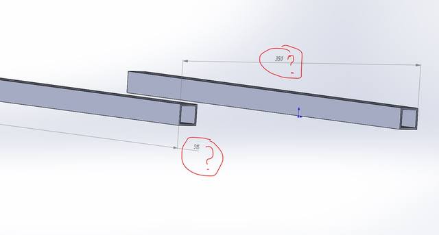
Vitolds wrote:length - 515 mm
width -?
Pipe 25x25x2 mm
For now I'm just creating the individual parts to put into assemblies later. We can fine tune the spacings etc. in the assemblies.
C5/6 A (complete)
Puma 40, 75Ah LiFePO4 (pic is on tour @ Whistler, BC)
Puma 40 backup, 73Ah MK (for now)
Spectra Plus (weedy 40Ah MK)
Puma 40, 75Ah LiFePO4 (pic is on tour @ Whistler, BC)
Puma 40 backup, 73Ah MK (for now)
Spectra Plus (weedy 40Ah MK)
-

Irving - Posts: 2114
- Joined: 04 Dec 2012, 11:51
- Location: NW London
Re: Lift and tilt project
![]() by Vitolds » 26 Mar 2020, 10:05
by Vitolds » 26 Mar 2020, 10:05
the width can be reduced or increased, the length cannot be reduced or increased.
We need to wait for an answer from Lenny.
We need to wait for an answer from Lenny.
- Vitolds
- Posts: 531
- Joined: 26 Mar 2014, 22:12
- Location: Moscow Russia
Re: Lift and tilt project
![]() by LROBBINS » 26 Mar 2020, 10:58
by LROBBINS » 26 Mar 2020, 10:58
I don't know if all the text annotations came across in the dxf exports or pdf derivatives, but the original Corel Draw files have lots of notes (to myself) that might be helpful. They are also drawn at 1:1 scale to (usually) sub-milimeter accuracy (and generally much more accurately than I can cut things), so one can just use Corel Draw's measurement tools. I keep a PC at the bench and usually use those measurements as I'm working rather than having to rely on transcribed-to-text measurements. Surely, if you have opened the dxf with a CAD program it will have similar measurement tools.
Checking just now, the overall length of both the lower and upper frames is 515 mm, width is 239 mm, and the lift bars are 440 mm long with bushings centered 12.5mm from the ends.
Length can, of course, also be changed from what I built and if I were building another I might well increase total length, and length of the lift bars, by perhaps 25 mm. And if I went to larger motors or larger tubing to handle more weight, that would pretty surely happen. If the tubes are strong enough (don't know that yet) I would, however, probably just change to a lift screw with 2mm pitch instead of 3mm - reducing motor torque (but also slowing the lift). It was hard enough to find these stock motors, and I don't want to repeat that exercise to find bigger ones. If I could get 30 mm square tubing instead of the 25 I'd do that too, and I'm pretty sure that, with the doubling along the inner lift bar where both walls are slotted, it could handle >150 kg. Another thing to consider, because the highest load is when the seat is starting from all the way down, would be to add helper springs for the initial lift movement.
- LROBBINS
- Posts: 5553
- Joined: 27 Aug 2010, 09:36
- Location: Siena, Italy
Re: Lift and tilt project
![]() by Vitolds » 26 Mar 2020, 12:30
by Vitolds » 26 Mar 2020, 12:30
Lenny, if you need to translate blueprints into solidworks, I'll do it.
If you want to resize and see how it will look, I will do it.
I don't need an elevator. I will not make it and I have no interest in it. I can make drawings to you if you need to.
I can make you drawings for laser cutting. Or for a bending machine.
If you want to resize and see how it will look, I will do it.
I don't need an elevator. I will not make it and I have no interest in it. I can make drawings to you if you need to.
I can make you drawings for laser cutting. Or for a bending machine.
- Vitolds
- Posts: 531
- Joined: 26 Mar 2014, 22:12
- Location: Moscow Russia
Re: Lift and tilt project
![]() by Irving » 26 Mar 2020, 12:41
by Irving » 26 Mar 2020, 12:41
I'm interested in making one, but i'd like to get it into solidworks so i can run animations and simulations to see where it can be pared down or beefed up as necessary & possibly 3D print parts in, for example, carbon-fibre filled nylon
C5/6 A (complete)
Puma 40, 75Ah LiFePO4 (pic is on tour @ Whistler, BC)
Puma 40 backup, 73Ah MK (for now)
Spectra Plus (weedy 40Ah MK)
Puma 40, 75Ah LiFePO4 (pic is on tour @ Whistler, BC)
Puma 40 backup, 73Ah MK (for now)
Spectra Plus (weedy 40Ah MK)
-
Irving - Posts: 2114
- Joined: 04 Dec 2012, 11:51
- Location: NW London
Re: Lift and tilt project
![]() by Irving » 26 Mar 2020, 13:34
by Irving » 26 Mar 2020, 13:34
Lenny a couple of questions if i may
How are the top outer bars joined to the cross piece, and is that cross-piece 239 - 2 x 25 = 189 long?
How long are the inner stub bars?
You say the overall length of the frames are 515mm, but the drawing shows the top outer bar is 480 long.
What is the POM slider?
How are the top outer bars joined to the cross piece, and is that cross-piece 239 - 2 x 25 = 189 long?
How long are the inner stub bars?
You say the overall length of the frames are 515mm, but the drawing shows the top outer bar is 480 long.
What is the POM slider?
C5/6 A (complete)
Puma 40, 75Ah LiFePO4 (pic is on tour @ Whistler, BC)
Puma 40 backup, 73Ah MK (for now)
Spectra Plus (weedy 40Ah MK)
Puma 40, 75Ah LiFePO4 (pic is on tour @ Whistler, BC)
Puma 40 backup, 73Ah MK (for now)
Spectra Plus (weedy 40Ah MK)
-
Irving - Posts: 2114
- Joined: 04 Dec 2012, 11:51
- Location: NW London
Re: Lift and tilt project
![]() by LROBBINS » 26 Mar 2020, 15:33
by LROBBINS » 26 Mar 2020, 15:33
That crossbar is only temporary - it is there just to hold the spacing between the outer bars. It has 3mm gussets riveted and epoxied underneath but is just held to the outer bars by by M4 bolts tapped into the outer bars. Once the seat pan is made, it will be held by M5 tapped into the Al blocks epoxied into the ends of the outer tubes. Depending on how I decide to mount the foot plate, the cross bar may be retained (to attach the foot plate bars with a stainless piano hinge?) or removed and the foot plate attached with M4 x 40 through the same Al block and tapped into Al blocks in the foot plate arms. If the cross bar is kept, it will be attached with M6 x 30 FH and nutsHow are the top outer bars joined to the cross piece, and is that cross-piece 239 - 2 x 25 = 189 long?
Yes, the tubular part of the cross piece is 189 mm long.
The original drawings and some of the initial assembly had most everything held together by epoxy and rivets - until I discovered just how often I'd need to dis-assemble and re-assemble it, when that got replaced by bolts, where possible through Al plugs so I can torque them tight without crushing the tubes.
The stub bars on the upper frame started as 292 mm long, but were trimmed (beveled) with dremel cutoff wheel after I discovered interference with the lift bars when down. Final length may be a bit shorter. Stub tubes on the lower frame were 222, but also beveled (less so than the upper stubs).How long are the inner stub bars?
You are quite correct; the upper side bars are shorter than the lower ones. Actual length is 482 mm (and you'll notice other 2 mm differences above). My drawings of the tubes used 2mm thick lines centered on what shows in the wireframe, so a wireframe of 23 mm x 480 mm is a finished tube size of 25 mm x 482 mm. (I didn't get so fancy as to split the rectangles and have 2mm lines at the side and hairlines at the ends.You say the overall length of the frames are 515mm, but the drawing shows the top outer bar is 480 long.
The sliders are cut from nominal 20 mm thick POM (acetal or Delrin if you prefer the brand-name stuff) sheet stock (which, as delivered is always >21 mm). They are 50 mm x 23 mm x 21+ mm and then hand milled (dremel burr and very course double cut file) for a free slip fit in the tubes. They are blind drilled or through drilled (as appropriate) a full 0.5 mm undersize and reamed for a tight fit of the 8mm dowels. Reaming POM needs slow speed and high feed or dimensions will be way off because of heating.What is the POM slider?
- LROBBINS
- Posts: 5553
- Joined: 27 Aug 2010, 09:36
- Location: Siena, Italy
Re: Lift and tilt project
![]() by LROBBINS » 26 Mar 2020, 15:37
by LROBBINS » 26 Mar 2020, 15:37
Is carbon fiber filled nylon more or less rigid than 6082? I had though of changing the lift tubes (which are the only highly stressed ones) to carbon fiber/epoxy but what's readily available has only a 1mm wall (at most), having them custom made would be too costly, and I don't know whether they are smooth and uniform enough inside for the sliders.
- LROBBINS
- Posts: 5553
- Joined: 27 Aug 2010, 09:36
- Location: Siena, Italy
Re: Lift and tilt project
![]() by Irving » 26 Mar 2020, 18:40
by Irving » 26 Mar 2020, 18:40
LROBBINS wrote:Is carbon fiber filled nylon more or less rigid than 6082? I had though of changing the lift tubes (which are the only highly stressed ones) to carbon fiber/epoxy but what's readily available has only a 1mm wall (at most), having them custom made would be too costly, and I don't know whether they are smooth and uniform enough inside for the sliders.
Its a good alternative to Al in certain situations. How useful here depends on loadings...
Any reason you're using 6082 or is that what you had in stock?
Oh, BTW, what is the length of the top inner tubes?
Also, if I read your drawing correctly, the slot on the inside of the outer tube is partially covered by the stub epoxied to it?
C5/6 A (complete)
Puma 40, 75Ah LiFePO4 (pic is on tour @ Whistler, BC)
Puma 40 backup, 73Ah MK (for now)
Spectra Plus (weedy 40Ah MK)
Puma 40, 75Ah LiFePO4 (pic is on tour @ Whistler, BC)
Puma 40 backup, 73Ah MK (for now)
Spectra Plus (weedy 40Ah MK)
-
Irving - Posts: 2114
- Joined: 04 Dec 2012, 11:51
- Location: NW London
Re: Lift and tilt project
![]() by LROBBINS » 26 Mar 2020, 19:29
by LROBBINS » 26 Mar 2020, 19:29
Irving,
6082 (or the U.S. near equivalent 6061) is the strongest of the 6000 alloys and is fairly readily available here, at least in a limited series of profiles. 6061 profiles are also rounded, which makes them difficult for this. U.S. 6063 profiles are square, but weaker as are the other European 6000 alloys. 7000 series might have been a better choice, but aside from a few sizes of sheet and solid round bars I can't get it in Italy without ordering hundreds of kilos.
For your other questions, I'll take a look at the drawings in a bit.
Vitold,
There are lots of linear slide components available, but, especially for that central joint that has to slide in both the front and rear lift bars, they'd be difficult to incorporate, or at least I couldn't think of a way to do so. This application really also doesn't need their low friction nor their precision.
- LROBBINS
- Posts: 5553
- Joined: 27 Aug 2010, 09:36
- Location: Siena, Italy
Re: Lift and tilt project
![]() by LROBBINS » 26 Mar 2020, 19:56
by LROBBINS » 26 Mar 2020, 19:56
OK Irving, I've looked at the drawings, but I'm not sure what you are asking.
Keep in mind that top and bottom frames are plan view projections so things that in real life are no where near each other are superposed in the drawings. For example, the dowels at the front of the outer lift tubes seem to enter the inner lift tubes - they don't. Same for the nut ends of the shoulder bolts at the rear.
The top frame has only two longitudinal bars. What the drawing shows are those two plus the two inner and two outer lift bars, and they are all 442 long. The inner lift bars have reinforcing tubes bonded and screwed on top at the rear. One of them is drawn off to the side. They are 238 mm long and tapered as shown. I hacked them out of some scrap, and one of them actually was an earlier mistake with a slider slot already cut in it, and then I further massacred them until I figured out how to mount the over-tilt limit switches in a way that they don't hit anything anywhere during the movement.Oh, BTW, what is the length of the top inner tubes?
I'm guessing that you are referring to the lower frame. The longitudinals are slotted on the inside only at the front, and the stub tubes mounted at the rear are slotted on the inside. There's no slot at the rear in the long tubes to be covered.Also, if I read your drawing correctly, the slot on the inside of the outer tube is partially covered by the stub epoxied to it?
Keep in mind that top and bottom frames are plan view projections so things that in real life are no where near each other are superposed in the drawings. For example, the dowels at the front of the outer lift tubes seem to enter the inner lift tubes - they don't. Same for the nut ends of the shoulder bolts at the rear.
- LROBBINS
- Posts: 5553
- Joined: 27 Aug 2010, 09:36
- Location: Siena, Italy
Re: Lift and tilt project
![]() by Vitolds » 26 Mar 2020, 23:06
by Vitolds » 26 Mar 2020, 23:06
I think that the aluminum profile is unreliable.
I realized that you do not need drawings?
I will try to make a drawing in solidworks on the shafts.
I realized that you do not need drawings?
I will try to make a drawing in solidworks on the shafts.
- Vitolds
- Posts: 531
- Joined: 26 Mar 2014, 22:12
- Location: Moscow Russia
Re: Lift and tilt project
![]() by Irving » 27 Mar 2020, 11:41
by Irving » 27 Mar 2020, 11:41
Lenny, I can you take 3/4 and top view photos so I can get a better idea of these relationships between bits? I
C5/6 A (complete)
Puma 40, 75Ah LiFePO4 (pic is on tour @ Whistler, BC)
Puma 40 backup, 73Ah MK (for now)
Spectra Plus (weedy 40Ah MK)
Puma 40, 75Ah LiFePO4 (pic is on tour @ Whistler, BC)
Puma 40 backup, 73Ah MK (for now)
Spectra Plus (weedy 40Ah MK)
-
Irving - Posts: 2114
- Joined: 04 Dec 2012, 11:51
- Location: NW London
Re: Lift and tilt project
![]() by LROBBINS » 27 Mar 2020, 13:01
by LROBBINS » 27 Mar 2020, 13:01
I can, but not today. The populated CAN system boards will be arriving today and I've cleared my workbench so that I can work on them; running basic tests on them and then assembling one complete one for me so that I can really test them. I'll also temporarily have to drive the motors directly from the power supply as the Power Distribution module has been completely disassembled and is awaiting the new boards. In the meantime, you'll have to use the Overview1 pdf file and your imagination.
- LROBBINS
- Posts: 5553
- Joined: 27 Aug 2010, 09:36
- Location: Siena, Italy
Re: Lift and tilt project
![]() by Irving » 27 Mar 2020, 14:20
by Irving » 27 Mar 2020, 14:20
No problem, though imagination is on short supply at the mo!
Good luck with the new boards, hope you don't find too many oopsies!
Good luck with the new boards, hope you don't find too many oopsies!
C5/6 A (complete)
Puma 40, 75Ah LiFePO4 (pic is on tour @ Whistler, BC)
Puma 40 backup, 73Ah MK (for now)
Spectra Plus (weedy 40Ah MK)
Puma 40, 75Ah LiFePO4 (pic is on tour @ Whistler, BC)
Puma 40 backup, 73Ah MK (for now)
Spectra Plus (weedy 40Ah MK)
-
Irving - Posts: 2114
- Joined: 04 Dec 2012, 11:51
- Location: NW London
Re: Lift and tilt project
![]() by LROBBINS » 27 Mar 2020, 19:40
by LROBBINS » 27 Mar 2020, 19:40
So far one error, and it was mine. The CAN controller/transceiver boards have a through-hole 16MHz crystal and my layout had it top layer even though all the ones I built by hand have it on the bottom - which is where it should be. The supplier did what the files said so I have to remove and re-solder 25 crystals.
- LROBBINS
- Posts: 5553
- Joined: 27 Aug 2010, 09:36
- Location: Siena, Italy
Re: Lift and tilt project
![]() by Irving » 27 Mar 2020, 20:38
by Irving » 27 Mar 2020, 20:38
LROBBINS wrote:So far one error, and it was mine. The CAN controller/transceiver boards have a through-hole 16MHz crystal and my layout had it top layer even though all the ones I built by hand have it on the bottom - which is where it should be. The supplier did what the files said so I have to remove and re-solder 25 crystals.
Oops, I've done that before too. Sometimes its hard to visualise the tracks, but double-sided components are an extra mind-bender. Presumably the tracks were laid out to accomodate it on the underside? I guess it wont work topside unless pinout is symettrical in some way?
C5/6 A (complete)
Puma 40, 75Ah LiFePO4 (pic is on tour @ Whistler, BC)
Puma 40 backup, 73Ah MK (for now)
Spectra Plus (weedy 40Ah MK)
Puma 40, 75Ah LiFePO4 (pic is on tour @ Whistler, BC)
Puma 40 backup, 73Ah MK (for now)
Spectra Plus (weedy 40Ah MK)
-
Irving - Posts: 2114
- Joined: 04 Dec 2012, 11:51
- Location: NW London
Re: Lift and tilt project
![]() by LROBBINS » 27 Mar 2020, 21:02
by LROBBINS » 27 Mar 2020, 21:02
Just a 2 pin crystal, so symmetrical, but on the top it sits over the loading caps and also won't fit the physical layout of the board on which it gets mounted. I'll have to flip it to the other side in the board layout (and re-do the traces cause they'll flip too) for any future orders.
- LROBBINS
- Posts: 5553
- Joined: 27 Aug 2010, 09:36
- Location: Siena, Italy
Re: Lift and tilt project
![]() by Arima » 27 Mar 2020, 21:26
by Arima » 27 Mar 2020, 21:26
Irving wrote:Welcome to the fundamental differences between 2D drawings and 3D solid modelling!
I'm glad I took the time to go back study more. It's going to be a big help going forward. You mentioned solidworks and animation in another post I think. Fusion is not suited for those task?
Thxs
- Arima
- Posts: 665
- Joined: 06 Nov 2019, 19:24
- Location: Olympia, Wa.
Re: Lift and tilt project
![]() by Vitolds » 28 Mar 2020, 14:10
by Vitolds » 28 Mar 2020, 14:10
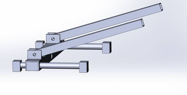
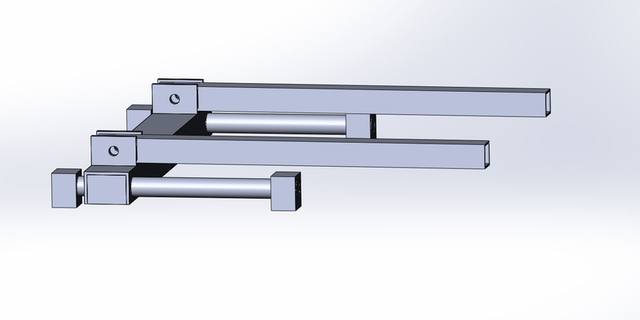
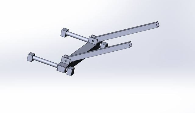
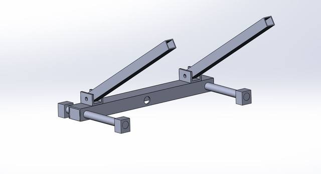
Schematically, the bottom of the frame.
if interested, I can continue.
This is just a diagram.
if interested, I can continue.
This is just a diagram.
- Vitolds
- Posts: 531
- Joined: 26 Mar 2014, 22:12
- Location: Moscow Russia
Re: Lift and tilt project
![]() by LROBBINS » 28 Mar 2020, 14:52
by LROBBINS » 28 Mar 2020, 14:52
You're certainly welcome to continue, and I'm certainly interested in seeing what you come up with.
It would be easy to use stock linear motion pieces for the lower frame sliders (though I think it will make minimum height a bit higher), but those tracks are under relatively little stress. The one that I see as a problem is the central pivot that has to slide in both the inner lift tubes (that go from bottom rear to top front) and the outer lift tubes (that go from bottom front to top rear), and it's the inner ones in particular that have critical bending stresses. Any design that will be strong enough, rigid enough, and smooth sliding for those inner lift bars will be more than adequate elsewhere. So I think it's that center sliding pivot that you should be thinking about. I would be very pleased to see you're solution for this.
It would be easy to use stock linear motion pieces for the lower frame sliders (though I think it will make minimum height a bit higher), but those tracks are under relatively little stress. The one that I see as a problem is the central pivot that has to slide in both the inner lift tubes (that go from bottom rear to top front) and the outer lift tubes (that go from bottom front to top rear), and it's the inner ones in particular that have critical bending stresses. Any design that will be strong enough, rigid enough, and smooth sliding for those inner lift bars will be more than adequate elsewhere. So I think it's that center sliding pivot that you should be thinking about. I would be very pleased to see you're solution for this.
- LROBBINS
- Posts: 5553
- Joined: 27 Aug 2010, 09:36
- Location: Siena, Italy
Re: Lift and tilt project
![]() by Vitolds » 28 Mar 2020, 15:24
by Vitolds » 28 Mar 2020, 15:24
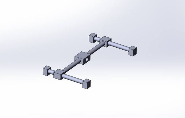
I understand that very well. this is a scheme so far.
I will make drawings, details that can be bought easily.
I will make drawings, details that can be bought easily.
- Vitolds
- Posts: 531
- Joined: 26 Mar 2014, 22:12
- Location: Moscow Russia
Re: Lift and tilt project
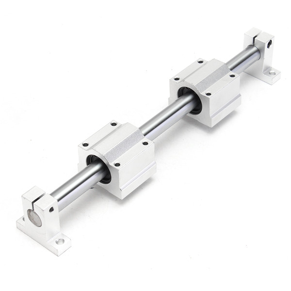
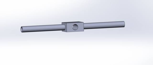
![]() by Vitolds » 28 Mar 2020, 15:42
by Vitolds » 28 Mar 2020, 15:42
bearing housing
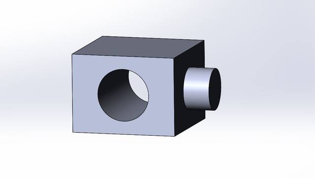
pipe for fastening a screw shaft
pipe for fastening a screw shaft
- Vitolds
- Posts: 531
- Joined: 26 Mar 2014, 22:12
- Location: Moscow Russia
Re: Lift and tilt project
![]() by ex-Gooserider » 31 Mar 2020, 06:25
by ex-Gooserider » 31 Mar 2020, 06:25
LROBBINS wrote:Is carbon fiber filled nylon more or less rigid than 6082? I had though of changing the lift tubes (which are the only highly stressed ones) to carbon fiber/epoxy but what's readily available has only a 1mm wall (at most), having them custom made would be too costly, and I don't know whether they are smooth and uniform enough inside for the sliders.
Not an expert, but in addition to having a Mark Forged printer, we have several folks at the Asylum who work for Mark Forged... Not to mention the BattleBot Valkyrie that is built at the Asylum and partly sponsored by MarkForged (I'm disappointed that this year's season is on hold thanks to Corona, as Valkyrie was already one of the scarier bots in the series, and is supposedly much improved this year....)
From what I have gathered talking to them, the Carbon fiber / nylon parts they can print are incredibly strong and rigid (probably more so than comparable Al sections) in the X-Y plane of the build where they can lay continuous strands of fiber at whatever density and in whatever pattern is required... However they are MUCH weaker in the Z axis as the layers can separate. This can be improved somewhat by post-print heating the entire print so that the layers can fuse together better, but it is still a problem that is inherent since they can't lay fiber in that axis....
I don't know if printing a square tube (which might also be a problem to clean any support infill out of the center afterwards) would give the strength you need Lenny.... Perhaps this is something the Mark Forged tech support people can help with (I'm not sure what their current operation status is due to Corona, but...)
ex-Gooserider
T-5, ASIA-B
Jazzy 1100
Jazzy Select 6
Quickie Q-7
Invacare Mariner
Want to make / get a better chair, ideally one that stands.
Jazzy 1100
Jazzy Select 6
Quickie Q-7
Invacare Mariner
Want to make / get a better chair, ideally one that stands.
-

ex-Gooserider - Posts: 5966
- Joined: 15 Feb 2011, 06:17
- Location: Billerica, MA. USA
Re: Lift and tilt project
![]() by Irving » 02 Apr 2020, 19:19
by Irving » 02 Apr 2020, 19:19
1st pass on full SolidWorks model
C5/6 A (complete)
Puma 40, 75Ah LiFePO4 (pic is on tour @ Whistler, BC)
Puma 40 backup, 73Ah MK (for now)
Spectra Plus (weedy 40Ah MK)
Puma 40, 75Ah LiFePO4 (pic is on tour @ Whistler, BC)
Puma 40 backup, 73Ah MK (for now)
Spectra Plus (weedy 40Ah MK)
-
Irving - Posts: 2114
- Joined: 04 Dec 2012, 11:51
- Location: NW London
Re: Lift and tilt project
![]() by LROBBINS » 02 Apr 2020, 21:16
by LROBBINS » 02 Apr 2020, 21:16
Hi Irving,
Good job on the structure, but the motion doesn't match the prototype (but, see below, what you've done may be worth some further thought).
In the prototype, the lower sliders are driven by a single motor and single lead screw - with a right hand thread at one end and a left hand thread at the other. If the front lower sliders move back, the rear lower sliders move forward by the same amount; the distance between them changes, but the mid-point remains fixed.
What you've drawn would require two motors and two lead screws. I don't know how I'd fit a second motor at the front without getting in the way of the user's legs, but if one could the added complexity might offer an advantage. It would allow one to shift CG forward as tilt goes back. The added complexity is not only in the mechanicals, but in the programming and sensing as well; as it is now I only sense rate of change of tilt, but don't have to know actual tilt angle. More limit switches would be needed as well. I will try to think about that, but in the meantime I think you should try to synchronize the movements of the lower sliders to each other in the way that the left-hand/right-hand lead screw does and see if you can work out the stresses involved.
- LROBBINS
- Posts: 5553
- Joined: 27 Aug 2010, 09:36
- Location: Siena, Italy
105 posts
• Page 2 of 4 • 1, 2, 3, 4
Return to Everything Powerchair
Who is online
Users browsing this forum: No registered users and 123 guests