14 power?
21 switched?
Yes you could, but when NOT switched it should be pulled "low" with a high value resistor.
I would use a series R1k from the 5v just in case of short etc in the connector, and say R10k (or more), pulled pin 21 to ground, so that when not switched to 5v it doesn't float to "on" point due to noise etc.
PINNED - Roboteq Controller - developing for powerchairs
Re: Some thinking and questions about Roboteq
![]() by Burgerman » 23 Feb 2014, 22:22
by Burgerman » 23 Feb 2014, 22:22
-

Burgerman - Site Admin
- Posts: 69892
- Joined: 27 May 2008, 21:24
- Location: United Kingdom
Re: Some thinking and questions about Roboteq
![]() by Williamclark77 » 24 Feb 2014, 03:43
by Williamclark77 » 24 Feb 2014, 03:43
So, on my switch that has three wires where red is positive, black is negative, and yellow is accessory - I would wired the red wire to pin 14 (5v out, pr any 5v out), black wire to pin 5 (ground, or any ground pin), and the yellow wire to pin 21 (Din, or any digital in pin) with a resistor in the ground wire? Sorry. I just want to be sure.
It is an led lighted switch. Light on when switched on.
It is an led lighted switch. Light on when switched on.
-

Williamclark77 - Posts: 1169
- Joined: 21 Mar 2013, 01:18
- Location: South Mississippi, United States
Re: Some thinking and questions about Roboteq
![]() by LROBBINS » 24 Feb 2014, 09:58
by LROBBINS » 24 Feb 2014, 09:58
NO. I think that you will short 5V to Ground when you press the switch if you wire it that way. If so, you WILL fry something. The Red and Black wires are most likely the normally-open switch contacts. The only reason one is marked "minus" is that it probably has the LED cathode connected to it so has to go to ground if you want to use the LED. The yellow wire would then be fed a voltage suitable for the LED.
DO read the Roboteq manual's pages AND get a diagram or description of that switch and the way the LED is wired: where does it get power from? is there already a current-limiting resistor? for what input voltage? If the black lead is the ground (cathode) of the LED, and you want the LED to light, you will have to use this as a LOW SIDE switch: pull up resistor to 5V then to switch (probably red), that same switch contact connected to the digital in, and the other side of the switch connected to ground -- see the Roboteq manual.
Next, with an ohmmeter, confirm which two contacts close when you push the button, then wire those the way Roboteq says to do it (the Roboteq description is pretty muddy, but eventually comprehensible). Burgerman is right that a series resistor is also a good idea, and it is mentioned in the manual although not shown in the diagram. Roboteq recommends it just in case a pin will be swap between digital-in and digital-out functions so that you can't create a 5v-GND short during that transition, but it would protect you from having the switch wired 5V-GND too.
Ciao,
Lenny
- LROBBINS
- Posts: 5774
- Joined: 27 Aug 2010, 09:36
- Location: Siena, Italy
Re: Some thinking and questions about Roboteq
![]() by Burgerman » 24 Feb 2014, 10:45
by Burgerman » 24 Feb 2014, 10:45
If if it makes it simpler to understand, you could alternatively pull the signal pin high to 5v with a 10k resistor inside the connector, and connect ground it through the switch to pull it low when you operate the switch. The roboteq doesn't care which way. You just tell it in programming.
Then you only have a 5v and series safety resistor, going to the switch just for the LED.
Then you only have a 5v and series safety resistor, going to the switch just for the LED.
-
Burgerman - Site Admin
- Posts: 69892
- Joined: 27 May 2008, 21:24
- Location: United Kingdom
Re: Some thinking and questions about Roboteq
![]() by Burgerman » 24 Feb 2014, 11:07
by Burgerman » 24 Feb 2014, 11:07
You need to do the same with the brake system, for eg. And any other input or output you use.
I am using 2 solid state relays. One to work the brakes, which are 12v, from a 45v battery via an inverter, one to switch the contactor at 12v in the event of a fault both manually and via a fault detection pin on the roboteq. Its not wise to switch the brake directly.
I am using 2 solid state relays. One to work the brakes, which are 12v, from a 45v battery via an inverter, one to switch the contactor at 12v in the event of a fault both manually and via a fault detection pin on the roboteq. Its not wise to switch the brake directly.
-
Burgerman - Site Admin
- Posts: 69892
- Joined: 27 May 2008, 21:24
- Location: United Kingdom
Re: Some thinking and questions about Roboteq
![]() by Williamclark77 » 24 Feb 2014, 17:16
by Williamclark77 » 24 Feb 2014, 17:16
Sadly, I have read those exact pages numerous times and have the switch's wiring diagram. I'm not confident enough in my comprehension of it to do any connecting yet. When I update my build thread I will show how to blow the mosfets in a Roboteq controller. That had nothing to do with a lack of understanding, but merely an accident. I can't afford another costly mistake like that regardless if it's from ignorance or accidental. I'm gun shy now.
This is the switch's wiring diagram:

When ordered prewired it comes with three wires labeled red (+), black (-), and yellow (accessory). There is no built in resistor as far as the specs say, just a 12v max warning. No external power used. Only the three connections inside the 25 pin Roboteq plug.
When connected to an ohmmeter I get:
Red/black = Switched on lights up the led. Off does nothing.
Yellow/black = led lights up in both the on and off position.
Red/yellow = Continuity buzz when on. Nothing when off.
Other than the rc and joystick connections, this limit switch will probably be the only connections I use inside the 25 pin plug.
This is the switch's wiring diagram:
When ordered prewired it comes with three wires labeled red (+), black (-), and yellow (accessory). There is no built in resistor as far as the specs say, just a 12v max warning. No external power used. Only the three connections inside the 25 pin Roboteq plug.
When connected to an ohmmeter I get:
Red/black = Switched on lights up the led. Off does nothing.
Yellow/black = led lights up in both the on and off position.
Red/yellow = Continuity buzz when on. Nothing when off.
Other than the rc and joystick connections, this limit switch will probably be the only connections I use inside the 25 pin plug.
-
Williamclark77 - Posts: 1169
- Joined: 21 Mar 2013, 01:18
- Location: South Mississippi, United States
Re: Some thinking and questions about Roboteq
![]() by LROBBINS » 24 Feb 2014, 18:10
by LROBBINS » 24 Feb 2014, 18:10
That circuit diagram has 5 connections, so the pre-wired switch must have connected some of these to each other. There is also DEFINITELY a resistor in series with the LED if it can be supplied with 12V. Your ohmmeter test is also not complete enough to figure out what the pre-wiring connects given the fact that the LED is a diode and lets current go in only one direction. If you can repeat that, connecting the + and common meter leads first in one direction and then the other, we might be able to deduce how those 3 wires are connected. Alternatively, the supplier might be able to give you some more information about how the pre-wired version is wired.
You are in luck on one score though -- the LED will be much dimmer on 5V than it would be on 12V, but if it lights with just the voltage from an ohmmeter it might be bright enough to be usable on 5V. (On the other hand, will that LED even really be useful to you?)
What you want to connect to the Roboteq are the C1 (common) and NO (normally-open) pins, or the C1 and NC (normally-closed) pins, and you can do it either so that pushing the button pulls the digital input to 5V or pulls the digital input to GND, but the way the LED is wired inside that pre-wired switch may limit your choices. Once you know exactly how that switch is wired, or if you simply get rid of their "pre-wiring" and use the 5 contacts, I could then draw a schematic, post it, and John and others can critique it to make sure it's correct and safe.
Ciao,
Lenny
- LROBBINS
- Posts: 5774
- Joined: 27 Aug 2010, 09:36
- Location: Siena, Italy
Re: Some thinking and questions about Roboteq
![]() by Williamclark77 » 24 Feb 2014, 18:42
by Williamclark77 » 24 Feb 2014, 18:42
It dawned on me about testing it in both directions after I posted that. I can recheck when I'm back home.
Thank you very much! That's what specific layman's info I was looking for. I can't really disassembly the switch without destroying it. This led switch was mostly for aesthetics to match the others (that are not yet installed either, so I can still easily regroup) and had little function. A simple on/off two wire switch will serve the same purpose for all. Would one of you mind dumbing down connecting a basic two wire on/off toggle for my reassurance? Thank you again.
Thank you very much! That's what specific layman's info I was looking for. I can't really disassembly the switch without destroying it. This led switch was mostly for aesthetics to match the others (that are not yet installed either, so I can still easily regroup) and had little function. A simple on/off two wire switch will serve the same purpose for all. Would one of you mind dumbing down connecting a basic two wire on/off toggle for my reassurance? Thank you again.
-
Williamclark77 - Posts: 1169
- Joined: 21 Mar 2013, 01:18
- Location: South Mississippi, United States
Re: Some thinking and questions about Roboteq
![]() by woodygb » 24 Feb 2014, 18:50
by woodygb » 24 Feb 2014, 18:50
Wired like this perhaps.

Why not just remove the shrink wrap and look ?
Why not just remove the shrink wrap and look ?
-

woodygb - Posts: 7128
- Joined: 12 Mar 2011, 18:45
- Location: Bedford UK
Re: Some thinking and questions about Roboteq
![]() by Williamclark77 » 24 Feb 2014, 23:10
by Williamclark77 » 24 Feb 2014, 23:10
Thanks Woody. I just cut the heat shrink off of one of the switches. I wasn't near the switches when I posted my last reply and was thinking there was more to getting a look at the wiring than cutting off some layers of heat shrink.
I can forgo these switches and use two wire on/off toggles instead if they would be simpler.


I can forgo these switches and use two wire on/off toggles instead if they would be simpler.
-
Williamclark77 - Posts: 1169
- Joined: 21 Mar 2013, 01:18
- Location: South Mississippi, United States
Re: Some thinking and questions about Roboteq
![]() by woodygb » 25 Feb 2014, 00:01
by woodygb » 25 Feb 2014, 00:01
It's wired like this then ..Red positive in ..Yellow switched positive out & LED on
- switch.png (225.14 KiB) Viewed 8530 times
-
woodygb - Posts: 7128
- Joined: 12 Mar 2011, 18:45
- Location: Bedford UK
Re: Some thinking and questions about Roboteq
![]() by LROBBINS » 25 Feb 2014, 10:40
by LROBBINS » 25 Feb 2014, 10:40
Looks like Woody's got it. Just to be sure though, you can use your ohmmeter to make one final check. Connect ohmmeter red (+) to switch RED and ohmeter black (COM) to switch BLACK and the LED should behave the way you already saw: switch open, no light, switch closed, LED lights. Reverse the ohmmeter leads and the LED should remain dark no matter whether the switch is pushed or not.
I have a few things to get done first, but soon as I can I'll make up a schematic diagram of how to wire it to the Roboteq. The RED will go to Roboteq 5V, the YELLOW to Roboteq digital input, and the BLACK to Roboteq ground, but a couple resistors will also be needed for safety and noise resistance. The LED will work, but will be rather dim at 5V (indeed, less than 5V with the added resistor).
This is a momentary contact switch, and I gather that you want it to work as push once = set Roboteq to inhibit, push again = set Roboteq to full. That means that your script will have to keep track of whether the switch had already been pushed. It would probably be a good idea to also build some de-bounce into the script as a mechanical switch actually makes a series of rapid close/open actions when you first push it, and you don't want the processor, which can be very fast, to read each push as a series of switch closures. If you don't know how to do that programming, you can either learn how or use a mechanical toggle switch or push-on/push-off switch instead.
Ciao,
Lenny
- LROBBINS
- Posts: 5774
- Joined: 27 Aug 2010, 09:36
- Location: Siena, Italy
Re: Some thinking and questions about Roboteq
![]() by woodygb » 25 Feb 2014, 11:47
by woodygb » 25 Feb 2014, 11:47
...Ummm ..I'm not so sure Lenny ..I thought it was a simple ON/OFF latching switch... but I could be wrong.This is a momentary contact switch
-
woodygb - Posts: 7128
- Joined: 12 Mar 2011, 18:45
- Location: Bedford UK
Re: Some thinking and questions about Roboteq
![]() by LROBBINS » 25 Feb 2014, 12:03
by LROBBINS » 25 Feb 2014, 12:03
Here's a diagram. Please, everyone, check that I haven't screwed up!
R1 (470 ohm) is a current limiter that protects the Roboteq pin (almost) no matter what.
R2 is a pull-down resistor to make sure the digital input is solidly low when the switch is open - for noise resistance.
R3 is the internal resistor inside the switch.
This arrangement will have the digital input LOW when the switch is open, and HIGH when the switch is closed - set up the Roboteq accordingly.
Ciao,
Lenny
- Roboteq DIN switch.jpg (28.8 KiB) Viewed 8508 times
R1 (470 ohm) is a current limiter that protects the Roboteq pin (almost) no matter what.
R2 is a pull-down resistor to make sure the digital input is solidly low when the switch is open - for noise resistance.
R3 is the internal resistor inside the switch.
This arrangement will have the digital input LOW when the switch is open, and HIGH when the switch is closed - set up the Roboteq accordingly.
Ciao,
Lenny
- LROBBINS
- Posts: 5774
- Joined: 27 Aug 2010, 09:36
- Location: Siena, Italy
Re: Some thinking and questions about Roboteq
![]() by woodygb » 25 Feb 2014, 12:20
by woodygb » 25 Feb 2014, 12:20
Looks ok to me Lenny.
The description of the switch is a little confusing ...
It would seem that the mechanical action of the button is momentary ( returns to original position after being pressed ) and the electrical attribute is latching...the LED being lit denoting ON.
The description of the switch is a little confusing ...
12V Blue LED Metal Switch Push Button Latching Momentary 16mm
It would seem that the mechanical action of the button is momentary ( returns to original position after being pressed ) and the electrical attribute is latching...the LED being lit denoting ON.
-
woodygb - Posts: 7128
- Joined: 12 Mar 2011, 18:45
- Location: Bedford UK
Re: Some thinking and questions about Roboteq
![]() by LROBBINS » 25 Feb 2014, 13:38
by LROBBINS » 25 Feb 2014, 13:38
Odd description indeed. Is it latching or momentary? If latching, there's less need for programming sleight-of-hand; even debounce might not be needed.
Ciao,
Lenny
Ciao,
Lenny
- LROBBINS
- Posts: 5774
- Joined: 27 Aug 2010, 09:36
- Location: Siena, Italy
Re: Some thinking and questions about Roboteq
![]() by Burgerman » 25 Feb 2014, 16:16
by Burgerman » 25 Feb 2014, 16:16
I have some of those switches. Didn't use them for powerchair stuff as they are big and heavy. But they are both latching and momentary. There are two types.
-
Burgerman - Site Admin
- Posts: 69892
- Joined: 27 May 2008, 21:24
- Location: United Kingdom
Re: Some thinking and questions about Roboteq
![]() by Williamclark77 » 25 Feb 2014, 17:24
by Williamclark77 » 25 Feb 2014, 17:24
Thank you all very much for your time! It is truly appreciated. Lenny, that is a diagram that even an electrically ignorant layman like myself can easily comprehend. It will be put to use in a few days when my new controller arrives. I should have my brushless chair back going this weekend. I decided to wait about getting it powdercoated until all of the kinks are worked out. Mechanically it has worked near perfect thus far and I haven't hit any major snags in my original design other than having to redo the caster forks. For all intents and purposes that part is basically finished. Electrically nothing major, but finalizing all of the little things, like this switch, is proving time consuming and frustrating.
Those switches are available as latched or momentary. I see some of the ebay sellers stock both and you say which you want when you order. Mine are all latched. I needed them latched to control other things.
Off

On. Crappy picture and looks very recessed, but the button is still easily switched off by pushing against the face of it with the heel of my hand or quad hand knuckle.

Those switches are available as latched or momentary. I see some of the ebay sellers stock both and you say which you want when you order. Mine are all latched. I needed them latched to control other things.
Off
On. Crappy picture and looks very recessed, but the button is still easily switched off by pushing against the face of it with the heel of my hand or quad hand knuckle.
-
Williamclark77 - Posts: 1169
- Joined: 21 Mar 2013, 01:18
- Location: South Mississippi, United States
Re: Some thinking and questions about Roboteq
![]() by LROBBINS » 25 Feb 2014, 20:10
by LROBBINS » 25 Feb 2014, 20:10
Good, so you needn't have state variables in your sketch to do the latching in software.
Glad to be of help.
Ciao,
Lenny
Glad to be of help.
Ciao,
Lenny
- LROBBINS
- Posts: 5774
- Joined: 27 Aug 2010, 09:36
- Location: Siena, Italy
Re: Some thinking and questions about Roboteq
![]() by Irving » 26 Feb 2014, 18:27
by Irving » 26 Feb 2014, 18:27
Its a rare mechanical switch that doesn't need debouncing. I agree non-latching pushbuttons always do, but even big chunky toggles invariably do. Anyway, IMHO, its good programming practice to always debounce a switched input!LROBBINS wrote:Odd description indeed. Is it latching or momentary? If latching, there's less need for programming sleight-of-hand; even debounce might not be needed.
Ciao,
Lenny
-

Irving - Posts: 2114
- Joined: 04 Dec 2012, 11:51
- Location: NW London
Re: Some thinking and questions about Roboteq
![]() by LROBBINS » 26 Feb 2014, 19:22
by LROBBINS » 26 Feb 2014, 19:22
Yes and no. As the switch will undoubtedly be polled once per loop and the chair and motors have a lot of inertia, the loop time itself often provides an adequate debounce. On my breadboard I've been re-using really cheesy tact switches without any deliberate de-bounce, but there's a ca. 0.2 msec loop time, and I haven't seen any false signals - I've never seen a series of CAN messages that say e.g. FWD, stop, FWD when the FWD button is pressed or the converse when it's released. Hence, I don't slow the loop any further or add processor overhead in order to de-bounce. In real use, the switches feed through 4066 analog switches that multiplex info to Rachi's computer as well as the chair, and mechanical bounce becomes pretty much irrelevant.
Ciao,
Lenny
Ciao,
Lenny
- LROBBINS
- Posts: 5774
- Joined: 27 Aug 2010, 09:36
- Location: Siena, Italy
Re: Some thinking and questions about Roboteq
![]() by Williamclark77 » 06 Mar 2014, 17:42
by Williamclark77 » 06 Mar 2014, 17:42
We got my chair back together and I spent all day Tuesday in it. I'm very impressed and quite proud of how well it functions. It's usable as is, but really needs a few programming touches to really round it out. To refresh your memory it is powered by 15ah Headway cells at 3p and 14s for ~48.3 working volts and 50.4 fully charged. My controller is the Roboteq hbl2360. My motors are Goldenmotor blt500 brushless trike motors.
BM was nice enough to email me a copy of the script a few months ago that yaw have compiled. It looks very impressive. Well over my head and coding ability. I have a few quick questions.
1. Motor compensation: My chair needs very little. I basically need enough to help it initiate a zero radius turn and starting from a dead stop on an incline. As is, for example stopped on a steep ramp, apply a little stick and it just binds. Apply a little more and WHEEEEELIE! For doing a zero turn, apply a little stick and it binds. Apply a little more and TORNADO! Both situation can be avoided by cleverly choosing my routes or turning at slight angles, but I know it can be done better.
In this line of code:
I have no idea of a good starting "motor resistance" point with brushless motors. My controller is configured to output 75 amps per channel. I can figure this out through trial and error, but if anyone knows of a good baseline I'm all ears.
Speed limiting: I picked up a 5k ohm potentiometer to use instead of the push button switch. I would prefer pot. I first thought it would be too difficult to program for a pot, but from skimming the code, it looks as if yaw have already included potentiometer speed reduction ability. Sooooo....
Would I change this line of code to true?
And would these lines of code need altering? Or am I correct in ASSuming these are the minimum and maximum speeds through the entire range of the pot from .2mv to 4800mv (or whatever it outputs when connected to the Roboteq's 5v source and output from the center pin on the pot to analog input 5 with a 220 ohm resistor)?
My joystick outputs a minimum of (roughly) 580mv and a max of 4100mv. Should I choose a higher ohm resistor accordingly to prevent disabling the chair outside either voltage with the pot (and coding to suit)? I currently have my Roboteq configured to emergency stop at 550mv and 4150mv. Wouldn't I lose quite a bit of resolution and motion if I changed the calibration's maximum and minimum values since the Roborun software doesn't let you put alternate min/max values as safety limiters. It goes off of the joystick's calibration values.
I don't intend for the Roboteq to do any type of battery monitoring. Do I still need to change the following line of code to match my battery, or ignore it? I'm unsure if code below this line will need to likewise be altered.
Clear as mud? Thanks for reading.
I'm off this weekend and HOPE to get this part of it done as well as pictures and video to update my build thread. Attached is a copy of the script I have in notepad format compressed to a .zip since .txt is not allowed in case mine is outdated or I copied it wrong. Should open in Notepad. Thanks again!
BM was nice enough to email me a copy of the script a few months ago that yaw have compiled. It looks very impressive. Well over my head and coding ability. I have a few quick questions.
1. Motor compensation: My chair needs very little. I basically need enough to help it initiate a zero radius turn and starting from a dead stop on an incline. As is, for example stopped on a steep ramp, apply a little stick and it just binds. Apply a little more and WHEEEEELIE! For doing a zero turn, apply a little stick and it binds. Apply a little more and TORNADO! Both situation can be avoided by cleverly choosing my routes or turning at slight angles, but I know it can be done better.
In this line of code:
- Code: Select all
vMotorResistance = 10          'MOTOR COMPENSATION. (SETTING THIS TOO HIGH IS DANGEROUS)
                               'Set to less than motor milliamps and then adjust based on chair response
I have no idea of a good starting "motor resistance" point with brushless motors. My controller is configured to output 75 amps per channel. I can figure this out through trial and error, but if anyone knows of a good baseline I'm all ears.
Speed limiting: I picked up a 5k ohm potentiometer to use instead of the push button switch. I would prefer pot. I first thought it would be too difficult to program for a pot, but from skimming the code, it looks as if yaw have already included potentiometer speed reduction ability. Sooooo....
Would I change this line of code to true?
- Code: Select all
bSpeedPotInstalled = FALSE 'Is speed potentiometer installed?
And would these lines of code need altering? Or am I correct in ASSuming these are the minimum and maximum speeds through the entire range of the pot from .2mv to 4800mv (or whatever it outputs when connected to the Roboteq's 5v source and output from the center pin on the pot to analog input 5 with a 220 ohm resistor)?
- Code: Select all
' CHARACTERISTICS OF SPEED POT
vPotMin = 20                   'speed at lowest pot setting
vSpeedPotLowFault = 10         'chair speed used if pot fails giving too low voltage
vSpeedPotHighFault = 70        'chair speed used if pot fails giving too high voltage
My joystick outputs a minimum of (roughly) 580mv and a max of 4100mv. Should I choose a higher ohm resistor accordingly to prevent disabling the chair outside either voltage with the pot (and coding to suit)? I currently have my Roboteq configured to emergency stop at 550mv and 4150mv. Wouldn't I lose quite a bit of resolution and motion if I changed the calibration's maximum and minimum values since the Roborun software doesn't let you put alternate min/max values as safety limiters. It goes off of the joystick's calibration values.
I don't intend for the Roboteq to do any type of battery monitoring. Do I still need to change the following line of code to match my battery, or ignore it? I'm unsure if code below this line will need to likewise be altered.
- Code: Select all
vFullRechargeVoltage = 449     'ten times battery voltage; 44.9V = 3.45V/cell - voltage present only immediately after
                               'recharging used to reset AmpHrs used measurement to 0
Clear as mud? Thanks for reading.
I'm off this weekend and HOPE to get this part of it done as well as pictures and video to update my build thread. Attached is a copy of the script I have in notepad format compressed to a .zip since .txt is not allowed in case mine is outdated or I copied it wrong. Should open in Notepad. Thanks again!
-
Williamclark77 - Posts: 1169
- Joined: 21 Mar 2013, 01:18
- Location: South Mississippi, United States
Re: Some thinking and questions about Roboteq
![]() by Williamclark77 » 06 Mar 2014, 17:47
by Williamclark77 » 06 Mar 2014, 17:47
My joystick outputs a minimum of (roughly) 580mv and a max of 4100mv. Should I choose a higher ohm resistor accordingly to prevent disabling the chair outside either voltage with the pot (and coding to suit)? I currently have my Roboteq configured to emergency stop at 550mv and 4150mv. Wouldn't I lose quite a bit of resolution and motion if I changed the calibration's maximum and minimum values since the Roborun software doesn't let you put alternate min/max values as safety limiters. It goes off of the joystick's calibration values.
I realized as soon as I hit reply that the pot will be on a separate input and not affect the joystick's calibration or min/max safety values. Disregard this point.
-
Williamclark77 - Posts: 1169
- Joined: 21 Mar 2013, 01:18
- Location: South Mississippi, United States
Re: Some thinking and questions about Roboteq
![]() by woodygb » 06 Mar 2014, 18:14
by woodygb » 06 Mar 2014, 18:14
Lenny will be along and give proper advice as it is his coding.
I do however think that milliamps may be a typo and it's milliohms.
I do however think that milliamps may be a typo and it's milliohms.
-
woodygb - Posts: 7128
- Joined: 12 Mar 2011, 18:45
- Location: Bedford UK
Re: Some thinking and questions about Roboteq
![]() by Burgerman » 06 Mar 2014, 18:33
by Burgerman » 06 Mar 2014, 18:33
Correct, its MY typo... They are just notes to help you know what does what, typed quickly...
I removed the script. There are unscrupulous people stealing Lennys hard work or wanting to do so, for commercial purposes, which I don't agree with.
MOhms is correct.
Start low, and you will gradually get more "power" at small stick movements. Add a bit at a time and test. OUTDOORS. So it should turn without needing a big handful. DONT add too much at once. You will regret that!
-
Burgerman - Site Admin
- Posts: 69892
- Joined: 27 May 2008, 21:24
- Location: United Kingdom
Re: Some thinking and questions about Roboteq
![]() by Williamclark77 » 06 Mar 2014, 18:54
by Williamclark77 » 06 Mar 2014, 18:54
I will just start working up from 1 tomorrow and try trial and error. I wasn't sure if brushless might require a vastly different figure compared to brushed that might take me all day to find going in small increments. We will see! Thank you.
It doesn't surprise me at all. Technology has devalued anything digital or software related. Quite a few of my photos have turned up for commercial uses without my consent or compensation. It's not even worth pursuing most times. Thank you for removing it. Feel free to edit my post accordingly and still get the point across.
Burgerman wrote:I removed the script. There are unscrupulous people stealing Lennys hard work or wanting to do so, for commercial purposes, which I don't agree with.
It doesn't surprise me at all. Technology has devalued anything digital or software related. Quite a few of my photos have turned up for commercial uses without my consent or compensation. It's not even worth pursuing most times. Thank you for removing it. Feel free to edit my post accordingly and still get the point across.
-
Williamclark77 - Posts: 1169
- Joined: 21 Mar 2013, 01:18
- Location: South Mississippi, United States
Re: Some thinking and questions about Roboteq
![]() by LROBBINS » 06 Mar 2014, 19:11
by LROBBINS » 06 Mar 2014, 19:11
Sounds like you are going to have a stupendous chair.
I haven't the time to look at that script right now, but I can say a couple general things.
First, do you know what the stall current of your motors are at some voltage (it needn't be the voltage you are using)? From that you can use ohms law to get an approximate measure of motor resistance. If you don't have that off a data sheet, you can measure it if you can run them at a lower voltage - e.g. 12 volts and measure the current draw. You have to measure the stall current with the motor in multiple positions around the circle and then use the highest current (= lowest resistance) you measure. I suggest lowering the voltage to make stalling easier and to avoid generating a lot of heat.
However, I don't know if adjusting motor compensation will solve your starting up problem. At very small stick movements, PWM is a small percent and battery current is low. As the Roboteq estimates motor current from PWM times battery current, it may be too inaccurate at small stick movements to get decent compensation. The cure for that would be adding external current sensors as described in the Roboteq manual. Until you get this sorted out, I'd suggest that you test with a lower current limit set and perhaps a lower supply voltage.
In the meantime, I'd suggest setting motor compensation to 0 and see if this makes the starting behavior worse, better or the same. If it's worse, the motors have a higher resistance than the number of mOhms I arbitrarily put in the script (unless Burgerman already changed that). If it's better, you were over compensating and you need a lower mOhm setting. If it's the same, your probably not actually getting any motor compensation at that point, probably because of the "iffiness" of estimating motor current from battery current. My guess is that you have too much compensation combined with no compensation near center because of the current estimation problem. If so, once the motor current gets high enough for the Roboteq to estimate it as other than zero, compensation is over-boosting it suddenly.
The above, of course, is all guesswork. How about coming to Siena and letting me play with the chair? Siena is usually beautiful this time of year, though this year it's been rain/grey/rain/grey - there's even lichen growing on our Chrysler.
Another thing you might play with is making the stick itself less sensitive near center - setting some level of exponential curving in the Roboteq. I don't think that this is a real cure for stall at low PWM, but it may make the jack rabbet-ness less intense.
The pot setting assumes that you have small fixed resistors between the two outer legs and your source voltage. That way, if a wire opens up it goes off scale and the script can do something with that. (I don't recall what I had in the script for speed pot out of range - whether it stops the chair or just sets a safe speed pot value. The latter is what I'm doing in the CAN bus controller I'm working on. I figure that if the pot fails you should at least be able to limp home rather than get stuck.) As you realized, the speed pot parameters do not affect the mV scaling of the joystick; the speed pot just scales the motor output by speed pot percentage of what the joystick is calling for.
Keep as detailed notes as you can on your testing and share them here. We all need to learn from what you're doing.
Ciao,
Lenny
- LROBBINS
- Posts: 5774
- Joined: 27 Aug 2010, 09:36
- Location: Siena, Italy
Re: Some thinking and questions about Roboteq
![]() by LROBBINS » 06 Mar 2014, 19:15
by LROBBINS » 06 Mar 2014, 19:15
John,
I don't mind if someone uses the script for commercial purposes as I have no interest in making any money at this. Of course, I do think that crediting the creator is the honest thing to do, and I surely wouldn't mind if someone who's found it useful decided to buy me a Roboteq.
Ciao,
Lenny
I don't mind if someone uses the script for commercial purposes as I have no interest in making any money at this. Of course, I do think that crediting the creator is the honest thing to do, and I surely wouldn't mind if someone who's found it useful decided to buy me a Roboteq.
Ciao,
Lenny
- LROBBINS
- Posts: 5774
- Joined: 27 Aug 2010, 09:36
- Location: Siena, Italy
Re: Some thinking and questions about Roboteq
![]() by woodygb » 06 Mar 2014, 19:41
by woodygb » 06 Mar 2014, 19:41
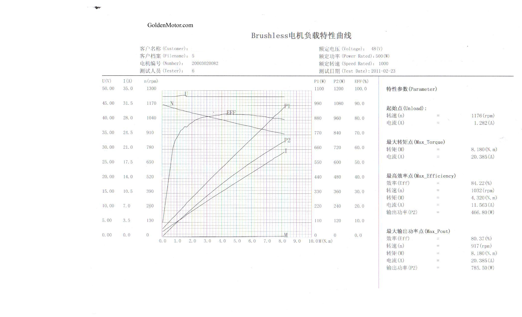
The only specs that I can find on the BLT 500 is here... unfortunately there isn't a MilliOhms value.
I did try deriving it but the two methods I tried gave widely diverging answers.
http://www.goldenmotor.com/hubmotors/BL ... 0Curve.jpg
I did try deriving it but the two methods I tried gave widely diverging answers.
http://www.goldenmotor.com/hubmotors/BL ... 0Curve.jpg
-
woodygb - Posts: 7128
- Joined: 12 Mar 2011, 18:45
- Location: Bedford UK
Re: Some thinking and questions about Roboteq
![]() by Williamclark77 » 06 Mar 2014, 21:25
by Williamclark77 » 06 Mar 2014, 21:25
As far as the motors go, this is all I've got as far as specs. The Chinese are not very forthcoming in documentation.

If I can't get acceptable performance using the motor compensation scripting then I'll see. I KNOW it's possible with the controller and motors. The "how" is the hard part. In closed loop torque mode the behavior is more predictable and smooth for the two circumstances I mentioned. Much like a conventional powerchair (as long as you're careful with how much joystick movement). Too bad torque mode is unacceptable everywhere else and I would prefer avoiding using any closed loop modes and extra sensors to fail.
My better half, Sommer, has been hounding me for two years about us taking a real vacation.... Careful what you wish
Already did that to get it as good as it is. A medium exponential curve on the throttle axis with no curve (linear) on the steering makes it turn at slight angles very well and easy to go straight at speed. As well as the Permobile I'm sitting in now. I can turn a pretty tight circle, just not zero turn like a bulldozer. Well, I can, but not without jack rabbiting. I also need to play with the actual mixed mode settings. Adding algo to the steering makes it "darty" at speed. Expo on the steering seems to just catch the throttle axis at the same point, just at a different amount of joystick input for the same result at low speeds.
The script looks to slow the chair down to either 20 or 70% for over or under voltage. I will pick some resistors up after work today. I won't be able to wire in the pot until this weekend when some better working hands (ie - Sommer) is also off to help and I've had time to study exactly how the resistors should be placed.
I will update my build thread with total progress and keep this thread Roboteq related. I'm off work tomorrow and plan to be in it all day. I'll have plenty of pictures and video to update my build thread with tomorrow night or Saturday morning - if the rain we have forcasted holds off.
Which model do you have in mind for Rachi's chair? I've been trying to keep up with what you've posted about it. Sadly, most of it is so far over my head, elektrickery wise, that I don't even know what questions to ask to start understanding it.
Thank you all very much for your time. I have enough info here to keep me busy for a few days.
If I can't get acceptable performance using the motor compensation scripting then I'll see. I KNOW it's possible with the controller and motors. The "how" is the hard part. In closed loop torque mode the behavior is more predictable and smooth for the two circumstances I mentioned. Much like a conventional powerchair (as long as you're careful with how much joystick movement). Too bad torque mode is unacceptable everywhere else and I would prefer avoiding using any closed loop modes and extra sensors to fail.
How about coming to Siena and letting me play with the chair?
My better half, Sommer, has been hounding me for two years about us taking a real vacation.... Careful what you wish
Another thing you might play with is making the stick itself less sensitive near center - setting some level of exponential curving in the Roboteq. I don't think that this is a real cure for stall at low PWM, but it may make the jack rabbet-ness less intense.
Already did that to get it as good as it is. A medium exponential curve on the throttle axis with no curve (linear) on the steering makes it turn at slight angles very well and easy to go straight at speed. As well as the Permobile I'm sitting in now. I can turn a pretty tight circle, just not zero turn like a bulldozer. Well, I can, but not without jack rabbiting. I also need to play with the actual mixed mode settings. Adding algo to the steering makes it "darty" at speed. Expo on the steering seems to just catch the throttle axis at the same point, just at a different amount of joystick input for the same result at low speeds.
That way, if a wire opens up it goes off scale and the script can do something with that. (I don't recall what I had in the script for speed pot out of range - whether it stops the chair or just sets a safe speed pot value.
The script looks to slow the chair down to either 20 or 70% for over or under voltage. I will pick some resistors up after work today. I won't be able to wire in the pot until this weekend when some better working hands (ie - Sommer) is also off to help and I've had time to study exactly how the resistors should be placed.
Keep as detailed notes as you can on your testing and share them here. We all need to learn from what you're doing
I will update my build thread with total progress and keep this thread Roboteq related. I'm off work tomorrow and plan to be in it all day. I'll have plenty of pictures and video to update my build thread with tomorrow night or Saturday morning - if the rain we have forcasted holds off.
I do think that crediting the creator is the honest thing to do, and I surely wouldn't mind if someone who's found it useful decided to buy me a Roboteq.
Which model do you have in mind for Rachi's chair? I've been trying to keep up with what you've posted about it. Sadly, most of it is so far over my head, elektrickery wise, that I don't even know what questions to ask to start understanding it.
Thank you all very much for your time. I have enough info here to keep me busy for a few days.
-
Williamclark77 - Posts: 1169
- Joined: 21 Mar 2013, 01:18
- Location: South Mississippi, United States
Return to Everything Powerchair
Who is online
Users browsing this forum: Kande_ian, LROBBINS, shirley_hkg and 110 guests