S646se - Full LITHIUM Pack Project - First Attempt

Power wheelchair board for REAL info!

POWERCHAIR MENU! www.wheelchairdriver.com/powerchair-stuff.htm

Re: S646se - Full Pack Project - First Attempt

Postby Burgerman » 12 Apr 2016, 00:45

the only wires i have left to attach are the Charge wires - i will use XT90 connector for that with 12 AWG wire also - same as the PL 8 charge wires -


Same QUALITY? as pl8 cable and silicone? Because those will need to be as they do get pretty warm.

And the END 2 on your extra cells are much better 10 gauge as you already understand?
User avatar
Burgerman
Site Admin
 
Posts: 69921
Joined: 27 May 2008, 21:24
Location: United Kingdom

Re: S646se - Full Pack Project - First Attempt

Postby Scollard » 12 Apr 2016, 00:47

It's no problem. Use the 12 AWG, make them longer so you can connect them to the big pack underneath the top pack. Bring the wire out from below and make a gentle curve to attach it to the top of the pack.

You also don't have to put the wire on the exact same row. For example. If you put one end of the wire on the left side of busbar 2, you can bring the wire out and put it on the right side of busbar 2 on the top pack. Whether it's on the left or right side of the busbar doesn't matter, it's all busbar 2. Only in rows 0 and 8 will you have to be on the exact same row because there is no busbar.
Scollard
 
Posts: 258
Joined: 29 Aug 2015, 01:43
Location: Seattle, WA

Re: S646se - Full Pack Project - First Attempt

Postby Burgerman » 12 Apr 2016, 01:27

No. No. Np. The top pack is not like an add-on. It is a 7th row. You should use the 12 AWG wires to attack all 0,1,2,3,4,5,6,7,8. You do not need bigger wires for positions 0 and 8. You want 12 AWG to wire in the top pack so when it comes time to balance there is minimal resistance accessing the 7th row cells. It's not going to be a good as having a busbar but it will be pretty close.


Yes it is exactly like an add on.

Provided its series wired. Every row is a 24v battery. (I am pretty sure thats what you did since 8s).
Electrically ALL rows are addons... When drawing power the up to 200A flows split through each set of cells in SERIES and out of the ENDS only. Thats up to 34A on expressos chairs 0 and 8 connections.

Just a tiny 1A current required to cross balance in between cells if needed flows via the parallel links. Unless the charger is balancing. So really tiny wires like the pl8 balance cables could be used on every cell connection other than 0 and 8. Even on the rest of the pack. If connections 1 to 7 were totally excluded the battery will perform just the same. But the cells would go out of balance in time.

Its no different to connecting a 7x 12v car batteries in parallel. In use theres no cross cell connection at all there, and if there was no current would flow during discharge.
User avatar
Burgerman
Site Admin
 
Posts: 69921
Joined: 27 May 2008, 21:24
Location: United Kingdom

Re: S646se - Full Pack Project - First Attempt

Postby ex-Gooserider » 12 Apr 2016, 02:48

I thing both Scollard and BM are right on this one... Hard though it seems...

BM is right in that every series row in a pack is an 'add-on' BUT the packs he is building for his own chairs tie all the series rows together with bus bars. He doesn't build a bunch of series rows, tie them together just at the ends with heavy wires and balance wires in the middle.... It WOULD work that way, but it is better with the bus bars as it distributes the current flow more evenly across the entire pack...

The 'extra row' that Expresso is adding is something that we would all connect to the rest of the pack with bus bars in both series and parallel, just like he did the main pack, if it were along side of it. Scollard simply wants to use heavy wires to replace the bus bars - or build it the same way as the rest of the pack...

Either way would work, but IMHO the heavy wires are better...

ex-Gooserider
T-5, ASIA-B
Jazzy 1100
Jazzy Select 6
Quickie Q-7
Invacare Mariner
Want to make / get a better chair, ideally one that stands.
User avatar
ex-Gooserider
 
Posts: 6197
Joined: 15 Feb 2011, 06:17
Location: Billerica, MA. USA

Re: S646se - Full Pack Project - First Attempt

Postby Burgerman » 12 Apr 2016, 02:59

BM is right in that every series row in a pack is an 'add-on' BUT the packs he is building for his own chairs tie all the series rows together with bus bars. He doesn't build a bunch of series rows, tie them together just at the ends with heavy wires and balance wires in the middle.... It WOULD work that way, but it is better with the bus bars as it distributes the current flow more evenly across the entire pack...


For the end 2 wires (0 and 8) heavy wires or bus bars would be ideal. It matches resistance etc. But anything 34A capable will be safe/ok to use. So 10 gauge or 12 if silicone and heat proof should be ok. The END connections + series connections are the only place current flows on charge or discharge. Any other connection is incidental, and only sees minute balance currents.

It WOULD work that way, but it is better with the bus bars as it distributes the current flow more evenly across the entire pack...


Negligible/no current flows in the parallel bus bars in use other than the tiny current needed to maintain balance. Micro amps unless charging and balancing at a max of 1A

The only reason to use bus bars in the main pack to tie the mid parallel cells together rather than super thin balance wires is because:
a) I have them, all over the bench so its easy! But a MAX of 1A flows here...
b) they are physically stronger so harder to break unnoticed and ruin a battery. Any tiny wire is fine for balance.
User avatar
Burgerman
Site Admin
 
Posts: 69921
Joined: 27 May 2008, 21:24
Location: United Kingdom

Re: S646se - Full Pack Project - First Attempt

Postby Scollard » 12 Apr 2016, 03:32

No. That is incorrect. If you were to measure the current at the battery wires that supply the chair and compare it to the current running through the wire connecting the 7th row to the large pack they would not be the same. So while 8 AWG is perfect for the chair connector the 12 AWG wire is suitable for attaching the 7th row because it will only ever wee a fraction of the total current draw by the chair.

This is why we talk about the C-rate of the cells. One 15 Ah cell at a draw of 10C can maintain a 150A draw. Ten 15 ah cells can maintain a 1500A draw. Why is that, well it's because each cell is only delivering 150A. The current is split among the parallel cells.
Scollard
 
Posts: 258
Joined: 29 Aug 2015, 01:43
Location: Seattle, WA

Re: S646se - Full Pack Project - First Attempt

Postby Burgerman » 12 Apr 2016, 03:59

No. That is incorrect. If you were to measure the current at the battery wires that supply the chair and compare it to the current running through the wire connecting the 7th row to the large pack they would not be the same.


Of course its not! It is 1/7th of the total that the charger or chair puts in or takes out. Since 7p. If all cells are healthy. With Expressos R-Net thats a peak of 120A per channel - 240A total and so div by 7 for 34Amps MAX.
Or higher if some cells in the main pack go high resistance over time. And we dont want a fire. 10 gauge is safer for 0 and 8. 12 gauge will be ok if really good termination and silicone cable. (no dodgy diy crimp)

Take a look. http://assets.bluesea.com/files/resourc ... hartlg.jpg

Remember the cable performs better than the terminal. And we are interested in safety. And this chart is for high temp quality marine cable. And thin cables heat fast. With heavy cables such as the main battery cable there is much more thermal mass that is adequate for intermittent over current. And its fused in case. So we get away with undersized cables here. (except invacare!)

This is why we talk about the C-rate of the cells. One 15 Ah cell at a draw of 10C can maintain a 150A draw. Ten 15 ah cells can maintain a 1500A draw. Why is that, well it's because each cell is only delivering 150A. The current is split among the parallel cells.


No its not. C rate refers to a bunch of things, relating to best max discharge or charge rate, internal resistance heating, service life, voltage drop etc. It has little to do with this. You can easily take out more than the rated C if you try... You are talking about internal resistance.

If you didnt bother connecting 1 to 7 cells to the main pack at all, there is no change in the current at 0 and 9 at the same load. 1 to 7 can be tiny wires. They do nothing in use.
User avatar
Burgerman
Site Admin
 
Posts: 69921
Joined: 27 May 2008, 21:24
Location: United Kingdom

Re: S646se - Full Pack Project - First Attempt

Postby expresso » 12 Apr 2016, 16:00

ex-Gooserider wrote:I thing both Scollard and BM are right on this one... Hard though it seems...

BM is right in that every series row in a pack is an 'add-on' BUT the packs he is building for his own chairs tie all the series rows together with bus bars. He doesn't build a bunch of series rows, tie them together just at the ends with heavy wires and balance wires in the middle.... It WOULD work that way, but it is better with the bus bars as it distributes the current flow more evenly across the entire pack...

The 'extra row' that Expresso is adding is something that we would all connect to the rest of the pack with bus bars in both series and parallel, just like he did the main pack, if it were along side of it. Scollard simply wants to use heavy wires to replace the bus bars - or build it the same way as the rest of the pack...

Either way would work, but IMHO the heavy wires are better...

ex-Gooserider


Right - you got it excatly how Scollard planned it out for me - its confusing maybe because its sitting on the top of the pack sideways - if i took the 7th row - and stand it up next to the last row of cells - it would be a 8p x 7S pack ?

the wires are just going to replace the buss bars - thats it - now since i tested the wiring last night - Scollard was right on the money with the length - 6 inch seems to work - i can attach the wire on the ends around the outside instead of under so i can use a thicker wire this way -

number 2 4 6 - i have to go under the pack - and it looks as if i can use 10 AWG - should fit the same - i was just about to finish up making the wires with 12 AWG - i will just use 10 AWG - and 8 AWG on the ends only 0 and 8

this way - we should be happy and all agree ??
Quickie 636 - 230ah LifePo4
expresso
 
Posts: 11985
Joined: 10 May 2010, 03:17

Re: S646se - Full Pack Project - First Attempt

Postby expresso » 12 Apr 2016, 16:19

I am confused a bit about this Balancing talk of the wires and the sections of the battery - i understand the ends 0 and 8 - those are the Big Boys - connected they make up the 27V - one Row of 8 Cells -
I have 6 Rows of those 8 Cells - each Row makes 27V - i get that

Each Row of 8 Cells - 6 wide are connected with the Buss Bars - pictures show it all -
now the 7th Row ideally would be next to the 6th Row - connected with the buss bars - making it 8P x 7S - if i am correct - because i dont know anymore :)

since i dont have room for the 7th Row on the side as it would be normally - We put it on the top flat - all thats needed is to connect that to the pack using wires instead of the buss bars -

my question now is - the wiring size - for the ends 0 and 8 - i am able to fit 8 AWG i believe - at least 10 but since i am looping the wire around the outside and back in - i may be able to get away with 8 AWG -

the rest of the inner cells 2 4 6 - Can i use 12 AWG there ? Since i already have 1 3 5 7 - connected to the bottom with 12 AWG - the bottom of the pack is done already - and i rather not have to have it flipped and taken apart now -

unless i have no choice -

here are the pics so far - i am going to hold off on making the rest of them till i hear back here - i welcome anyone to offer there opinion - i think Scollard and BM are correct also but then what do i know - i trust both -

what i will do is make the rest of the wires 12 AWG only for the 2 4 6 Cells - and 8 AWG for the ends ? or 10 AWG at worst case ?

whats the verdict before i try to finish the wiring -
Quickie 636 - 230ah LifePo4
expresso
 
Posts: 11985
Joined: 10 May 2010, 03:17

Re: S646se - Full Pack Project - First Attempt

Postby expresso » 12 Apr 2016, 16:19

pic
Quickie 636 - 230ah LifePo4
expresso
 
Posts: 11985
Joined: 10 May 2010, 03:17

Re: S646se - Full Pack Project - First Attempt

Postby expresso » 12 Apr 2016, 16:21

this cable with the XT90 connector end - is for charging with the balance wires - which i need to make the other end of that cable with the SubD for charging - i used 12 AWG for that - the same size as the Pl 8 charging cable with the built in fuse -

that should handle 40A charging if i wished to charge the fast - ?
Quickie 636 - 230ah LifePo4
expresso
 
Posts: 11985
Joined: 10 May 2010, 03:17

Re: S646se - Full Pack Project - First Attempt

Postby expresso » 12 Apr 2016, 17:43

Ok - will make the 0 and 8 - 8 AWG - 7 inches long -

the middle cells 2 4 6 - will be 12 AWG wire 6 inches long -

number 1 3 5 7 - already have 12 AWG wire done -

this should be correct and safe ?

When i hear balance wires - i think of the small 22 AWG that goes to the PL 8 for balancing - - those are in place on the first screw - i am using each screw down the line for each set of cables i connect - one screw would be free only - down the line of 0 and 8 - with no cables on it -

if i understand correctly better now - the Main power is coming and going from the Ends 0 and 8 - which is going to the Chairs Main power - thats taking and giving out the bulk - then it gets distributed along the other groups of Cells

1 - 7 - and those groups dont need as thick a wire - 12 AWG would be more than enough to handle the distribution for those - in place of the buss bars -

will go make the rest of those wires now -

thanks for all the input - suggestions
Quickie 636 - 230ah LifePo4
expresso
 
Posts: 11985
Joined: 10 May 2010, 03:17

Re: S646se - Full Pack Project - First Attempt

Postby Scollard » 12 Apr 2016, 19:40

Yep, you got it. Time to push for the finish.
Scollard
 
Posts: 258
Joined: 29 Aug 2015, 01:43
Location: Seattle, WA

Re: S646se - Full Pack Project - First Attempt

Postby Burgerman » 12 Apr 2016, 19:53

Yes.

i think of the small 22 AWG that goes to the PL 8 for balancing -


22 is big enough to replace all the "cross" bus bars on the entire pack, or to connect 1234567. (electrically). But a bit weak physically and may get damaged. So as you suggested is great. Those connections serve only to conduct tiny balance currents.

How is the original addon working?
User avatar
Burgerman
Site Admin
 
Posts: 69921
Joined: 27 May 2008, 21:24
Location: United Kingdom

Re: S646se - Full Pack Project - First Attempt

Postby expresso » 12 Apr 2016, 20:32

Scollard wrote:Yep, you got it. Time to push for the finish.


yes - getting scary now towards the end - i had a decent day of progress today - i finished up the cables for the front of the 7th Row - i have to just add the ends on the cables for the bottom row 1 3 5 7 - have to cut and add the ring -

will do on thursday - tomorrow i take a break -

i am waiting on heatshrink 1/4 size i need - for the next cable i make - which will be the chair part - one side anderson going to the right side of pack for add on in the future maybe

the other side - left side is the charge cable with subd - then i be ready to finish it up

the O and 8 cable is going to loop outside a bit - to keep it in a decent bend - i will add that on the last screw of the Row - replacing the cable thats there now - for the add on - will move that one up one screw instead -

so each connection has only one ring on it -
Quickie 636 - 230ah LifePo4
expresso
 
Posts: 11985
Joined: 10 May 2010, 03:17

Re: S646se - Full Pack Project - First Attempt

Postby expresso » 12 Apr 2016, 20:42

Scollard wrote:Yep, you got it. Time to push for the finish.


yes now i am getting worried - hope its all good i am starting to second guess myself now -
Quickie 636 - 230ah LifePo4
expresso
 
Posts: 11985
Joined: 10 May 2010, 03:17

Re: S646se - Full Pack Project - First Attempt

Postby expresso » 12 Apr 2016, 20:51

Burgerman wrote:Yes.

i think of the small 22 AWG that goes to the PL 8 for balancing -


22 is big enough to replace all the "cross" bus bars on the entire pack, or to connect 1234567. (electrically). But a bit weak physically and may get damaged. So as you suggested is great. Those connections serve only to conduct tiny balance currents.

How is the original addon working?


i used it yesterday - short run i had to do a few things - only put back about 16ah when recharged - all good - balance was perfect line - and it charged full down to the end nicely - ended - but was a short run - need warmer days to really test it - but i like it - works great - feels great - i am going to check my programming again - to make sure its all in check

and raise the toruge settings - originally all are set to 0 - i never touched them - - i dont want to over tax the motors so left them as is - but will raise it now and see


Question -

One set of cables i made - the Main pack going to the Chair Main - rings to anderson - 8 awg - when i made them - dont ask me why - i didnt dip it in the flux before i crimped them down with hydraulic crimper - i did wrap some thin solder around the wire to thicken it up a bit - i thinned it just a little so i can wrap the solder wire around it and snug fit i the ring and anderson end before crimping - then i torched it -

i keep thinking about that one and dont know why i changed the way i made the others - its connected - i checked the volts - all good -

what do you think of that - it should be good - pull test of course worked fine -
Quickie 636 - 230ah LifePo4
expresso
 
Posts: 11985
Joined: 10 May 2010, 03:17

Re: S646se - Full Pack Project - First Attempt

Postby Burgerman » 12 Apr 2016, 21:14

You should be ok if all parts were clean as theres a little flux in the solder. But how do you know its hot enough. I watch for solder to run at the end near the insulation then dip in water.
User avatar
Burgerman
Site Admin
 
Posts: 69921
Joined: 27 May 2008, 21:24
Location: United Kingdom

Re: S646se - Full Pack Project - First Attempt

Postby expresso » 12 Apr 2016, 21:22

Burgerman wrote:You should be ok if all parts were clean as theres a little flux in the solder. But how do you know its hot enough. I watch for solder to run at the end near the insulation then dip in water.


i stripped the wire - cut some off to thin it a bit so i can wrap the solder around the wire thats going in the ring or anderson - then stuck it in - crimped - and torched it - i was watching the end - and normally when i did it before - i cut the solder and wedged it in - but it was a tight fit - wasnt able to do that - thats the reason i wrapped it some -

so i watched it seen it get boiled - i stopped and dipped in water - it had a little fizz to it when i dipped - wasnt a huge fizz - :)

i didnt want to over do it and let it run back up the wire -

should be ok ?
Quickie 636 - 230ah LifePo4
expresso
 
Posts: 11985
Joined: 10 May 2010, 03:17

Re: S646se - Full Pack Project - First Attempt

Postby Burgerman » 12 Apr 2016, 21:43

It should. For future reference. DONT trim off strands. It makes the cable have a stress point and is more likely to fail. And you need only add a couple of strands of solder as it takes up too much volume and stops the cable crimping well. Ideally you would add none, and heat it and add it later to the joint. It takes a second only and no insulation melts if you dip it in water asap.
User avatar
Burgerman
Site Admin
 
Posts: 69921
Joined: 27 May 2008, 21:24
Location: United Kingdom

Re: S646se - Full Pack Project - First Attempt

Postby expresso » 12 Apr 2016, 21:55

Burgerman wrote:It should. For future reference. DONT trim off strands. It makes the cable have a stress point and is more likely to fail. And you need only add a couple of strands of solder as it takes up too much volume and stops the cable crimping well. Ideally you would add none, and heat it and add it later to the joint. It takes a second only and no insulation melts if you dip it in water asap.


i only trimmed it because it was a perfect fit but then cant add the solder - i seen the videos - dip in flux - crimp - heat the ring end till very hot and hold the solder at the end of the ring to flow inside - i never tired that yet -

or i can get larger rings - i find that using a 6 AWG ring for a 8 AWG wire - then i can stick the solder in and do it that way - -

i figure thin the wire just at the very end part - not alot just enough to add the solder in its place - - the heat shrink i used is very strong once dry - its glued down hard - wire isnt moving from there -

its not going to be pulled either hopefully not - once connected to the chair thats it - -

now the 2nd part of the cable i have to make - i am thinking 18 inches long - -
Quickie 636 - 230ah LifePo4
expresso
 
Posts: 11985
Joined: 10 May 2010, 03:17

Re: S646se - Full Pack Project - First Attempt

Postby Scollard » 12 Apr 2016, 23:09

Ok, we talk about flux a lot. If your wire has silver strands, not copper strands, but silver strands, flux is less of an issue. Flux is really used to clean off the copper oxidation. If your wires are tinned, and I mean it's tin that makes them silver, sometimes zinc (more so for terminals than stranded wire), flux doesn't do a lot. It may aid the solder to flow into the wire, but there is really no oxidation that it is cleaning away to make the contact better. Flux is really more important for bare copper. Any wires and fittings that are silver in color are typically very difficult to oxidize and really don't need additional flux beyond what's in the actual solder.
Scollard
 
Posts: 258
Joined: 29 Aug 2015, 01:43
Location: Seattle, WA

Re: S646se - Full Pack Project - First Attempt

Postby expresso » 12 Apr 2016, 23:20

Ok - i didnt tin the wires i made - the only wires i tinned before making a cable is the charge cable with the Sub D connector ends -

and those XT90 connector -


is it advised to tin the wire before crimping it and making the cable ? i though of that at first - to thin it so the solder is already on the wire - then stick it in the ring or anderson end - crimp and heat it -

but wasnt sure if that was correct - so i didnt do it that way -
Quickie 636 - 230ah LifePo4
expresso
 
Posts: 11985
Joined: 10 May 2010, 03:17

Re: S646se - Full Pack Project - First Attempt

Postby Scollard » 12 Apr 2016, 23:55

No, we're talking about different types of tinning. You never tin a stranded wire with solder before crimping. And I maintain that crimping properly into a marine terminal and then heat shrinking is better than soldering and heat shrinking.

It is likely that your stranded wire is silver in color and that is because it has been plated with tin. They do this because it will not oxidize like bare copper. That is why using marine grade wire is a good thing. No oxidation problems. If your stranded wire is copper in color then you should be using flux to clean off any oxidation on the copper.
Scollard
 
Posts: 258
Joined: 29 Aug 2015, 01:43
Location: Seattle, WA

Re: S646se - Full Pack Project - First Attempt

Postby expresso » 13 Apr 2016, 00:05

Ok - i should be fine then - all my wiring is silver in color - i have some 8 awg marine wire - but very hard to bend - so i used the silicone kind - all silver strands

i was just double guessing the main cable i made - which i didnt add the flux when i crimped it down and torched it - i am 99% sure it was hot enough to melt the thin solder i wrapped around the wire to be extra sure -

its nearing the end and i am thinking back on everything i did - etc, - so much happened - during this - - if i ever have to make another one - would be better at it now for sure - as long as its the same layout :)

thats the trick for me - and help from here also -
Quickie 636 - 230ah LifePo4
expresso
 
Posts: 11985
Joined: 10 May 2010, 03:17

Re: S646se - Full Pack Project - First Attempt

Postby Burgerman » 13 Apr 2016, 00:54

You know how it works now. You could do it without help. As soon as you stop being scared of that solder!
User avatar
Burgerman
Site Admin
 
Posts: 69921
Joined: 27 May 2008, 21:24
Location: United Kingdom

Re: S646se - Full Pack Project - First Attempt

Postby expresso » 13 Apr 2016, 01:11

yes i do know alot more than before thats for - but i still need help if i did more - i would try to do my best - before asking for help

simple layout like the 90ah pack - thats fine - adding this extra Row on top - was a bit of a challenge - but now i get it also - so can do that next time if needed

i do want to perfect the solder - better - and get correct lug sizes - maybe a bit larger to make it easier - or practice it the other way - no solder inside and just heat it and hold the solder at the end to let it flow in - that would be ideal -

i did get a bit better at soldering the xt90 connectors - those are pain - cant use thick wire - 12 awg is ideal size - 10 i used on one cable which can be done but harder


and that charge sub d - was a challenge for sure - have to make one for this next - and two more xt90 ends to finish this up

hopefully in 2 weeks - ready to test on charger
Quickie 636 - 230ah LifePo4
expresso
 
Posts: 11985
Joined: 10 May 2010, 03:17

Re: S646se - Full Pack Project - First Attempt

Postby shirley_hkg » 13 Apr 2016, 02:45

expresso wrote:Ok -


is it advised to tin the wire before crimping it and making the cable ? i though of that at first - to thin it so the solder is already on the wire - then stick it in the ring or anderson end - crimp and heat it -


May I suggest that it is totally wrong ?

To my knowledge in high school , solder is a poor conductor, compared with copper.

Good connection is Cu-Cu

With tinned wire, it will be Cu-Pb-Cu.

Furthermore, solder increase the size of the wire strands, so you are now cramping the solder instead.

After heating up and solder melted and flow away. Eventually, it is the limited solder inside, holding the wire to the connector, not by cramping.

Correct me if I'm wrong. ;)
shirley_hkg
 
Posts: 4482
Joined: 31 Dec 2010, 13:42

Re: S646se - Full Pack Project - First Attempt

Postby Burgerman » 13 Apr 2016, 02:56

Yes till the copper goes dull and oxydised. DIY tools and terminals from soft copper (that are zinc coated anyway to stop oxidation of the copper) are not tight enough to keep oxygen out. The solder prevents that oxidation, and makes sure that theres a much larger area in actual contact. So the resistance of the joint is lower than the wire. More area than cable cross section. And it stays that way. Amature crimping with cheap soft ring terminals or andersons (some) is hopeless.

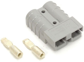
Some of the smaller anderson terminals for smaller wire are thick wall and can be crimped properly and need no solder.

These can, with the CORRECT hydralic tool, and with correct jaw size. thick walls. Hard to compress and difficult to crush even with a hammer. The cable cannot be pulled out and snaps first.
Image

These cannot just be crimped and must be soldered or they will oxidize and can be pulled out. They are thin walled and soft. Can be crushed even with pliers...
Image
User avatar
Burgerman
Site Admin
 
Posts: 69921
Joined: 27 May 2008, 21:24
Location: United Kingdom

Re: S646se - Full Pack Project - First Attempt

Postby expresso » 13 Apr 2016, 03:10

all this stuff is new to me - i hope all my cables are good now -

i though the goal was to make sure it will not come loose - - soldering is like having extra insurance ? - it feels very strong with the solder - but what do i know

i cant say either way - as long as my cables hold up now -
Quickie 636 - 230ah LifePo4
expresso
 
Posts: 11985
Joined: 10 May 2010, 03:17

PreviousNext

Return to Everything Powerchair

Who is online

Users browsing this forum: martin007, rover220, Yennek, yeshelp and 115 guests


  eXTReMe Tracker