I try the hard reset and then ran the debugging.
The debugging program does not receive any data from the Q-logic. "REC Freams" = 0, "Duty cycle" 0.
The only way I can send data with the debugging program is the "Send Buff". I tried this and it shows it sends the data. SendFream: = 1.
Q LOGIC PROGRAMMING INTERFACE
Re: Q LOGIC PROGRAMMING INTERFACE
![]() by jptrx » 23 Jul 2013, 00:51
by jptrx » 23 Jul 2013, 00:51
- jptrx
- Posts: 36
- Joined: 17 Jul 2012, 14:57
- Location: Canada
Re: Q LOGIC PROGRAMMING INTERFACE
![]() by jptrx » 23 Jul 2013, 01:07
by jptrx » 23 Jul 2013, 01:07
I also try setting the debbugging program to "loop back mode". Then send data on Buff 1 manualy. It both sends and receives the data successfully.
- jptrx
- Posts: 36
- Joined: 17 Jul 2012, 14:57
- Location: Canada
Re: Q LOGIC PROGRAMMING INTERFACE
![]() by gologen » 23 Jul 2013, 01:16
by gologen » 23 Jul 2013, 01:16
It looks you have communication problem between A1+ device and WC controller.
Check one more time CAN-H and CAN-L connection. Use short wires. Twist their.
Check one more time CAN-H and CAN-L connection. Use short wires. Twist their.
- gologen
- Posts: 112
- Joined: 11 Apr 2012, 12:46
- Location: Toronto Canada
Re: Q LOGIC PROGRAMMING INTERFACE
![]() by jptrx » 23 Jul 2013, 03:14
by jptrx » 23 Jul 2013, 03:14
OK, I will solder up a new cable tomorrow.
What do you use for the pins that plug into the XLR charging/programming port on the Q-logic joy stick?
I have used unplated steel spring pins that seem to fit pretty good. I would like to find something made from brass for better electrical conductivity.
What do you use for the pins that plug into the XLR charging/programming port on the Q-logic joy stick?
I have used unplated steel spring pins that seem to fit pretty good. I would like to find something made from brass for better electrical conductivity.
- jptrx
- Posts: 36
- Joined: 17 Jul 2012, 14:57
- Location: Canada
Re: Q LOGIC PROGRAMMING INTERFACE
![]() by gologen » 23 Jul 2013, 12:11
by gologen » 23 Jul 2013, 12:11
I use just the 2 pins from connector.
D 1.5mm
D 1.5mm
- pin.jpg (6.81 KiB) Viewed 21720 times
- gologen
- Posts: 112
- Joined: 11 Apr 2012, 12:46
- Location: Toronto Canada
Re: Q LOGIC PROGRAMMING INTERFACE
![]() by jptrx » 23 Jul 2013, 19:39
by jptrx » 23 Jul 2013, 19:39
Thanks for all your help Gologen.
I checked my connections and cable over really closely, and couldn't really find anything wrong, but I decided to make up a new cable anyway, just so I can be sure. Still no communication.
I think it's time to just order another A1+, for the cost of these we can't be too surprised if there are some bad ones. Hopefully not very often.
Woody: Do you think the Chinese A1+ is still the way to go for the Q-Logic, or do you have something better brewing in your lab? (:
- jptrx
- Posts: 36
- Joined: 17 Jul 2012, 14:57
- Location: Canada
Re: Q LOGIC PROGRAMMING INTERFACE
![]() by rubbertoe » 08 Aug 2013, 21:15
by rubbertoe » 08 Aug 2013, 21:15
Hello chaps,
One very big THANK YOU to all who posted on this thread, especially Woodygb who has help many, and me indirectly. After reading all post here and on the Buggiesgonewild site, and after 5 different usb-serial cables I’ve managed to connect to my Curtis 1228… I’m so glad, that I’ve chosen to share my experience in hope to help others too; here’s my path in brief (not sure if all steps are needed but it worked for me, on Windows Vista):
1) Got a copy of the software 1314 from Woody’s link http://www.yourfilelink.com/get.php?fid=786915
2) Got the files LXN4py2s.dll and QM_USB.dll from Woody’s first post and copied them in the directory specified
3) Bought the USB-Serial cable HL-340 from this chap on ebay £3.50 inc delivery. http://www.ebay.co.uk/itm/321110901546? ... 1439.l2649 (this cable was number 5 I bought… Belkin, Prolific chip based, Ttl, none of them work!!!!)
4) Cable didn’t come with driver so I installed the one found on this forum http://www.davesdrivers.com/forum/showt ... hp?tid=335 (post #3, file ch34rser.zip)
5) Bought the 4 pin Molex from Maplin and made the interface cable with an old 9 pin D plug, following the schematics download/file.php?id=2295
6) Plugged the cable and checked the port on Device Manager, also lowered the buffers value on the advanced properties of the port
7) Started up the 1314 software
8) Switch the controller on
9) Selected ‘Serial’ for protocol used and the same com port for the cable
Seems to work all the time… fingers crossed!! I can now get on with my project.
Thanks again guys!!
- rubbertoe
- Posts: 2
- Joined: 07 Aug 2013, 21:21
Re: Q LOGIC PROGRAMMING INTERFACE
![]() by woodygb » 08 Aug 2013, 22:21
by woodygb » 08 Aug 2013, 22:21
Ah .... The Curtis 1228 Mobility SCOOTER Controller doesn't need the LXN4py2s.dll and QM_USB.dll files as they are specific to the Q-Logic CanBus.
You should have asked ..one of these http://www.ebay.co.uk/itm/271072910237? ... 438.l2649= and the Molex is all you need.
The ebay cable is currently priced in error it's normally £1.79
You should have asked ..one of these http://www.ebay.co.uk/itm/271072910237? ... 438.l2649= and the Molex is all you need.
The ebay cable is currently priced in error it's normally £1.79
- SERIAL ADAPTOR INTERFACE curtis.jpg (138.04 KiB) Viewed 21571 times
-

woodygb - Posts: 7128
- Joined: 12 Mar 2011, 18:45
- Location: Bedford UK
Re: Q LOGIC PROGRAMMING INTERFACE
![]() by gologen » 09 Aug 2013, 11:56
by gologen » 09 Aug 2013, 11:56
woodygb wrote:You should have asked ..one of these http://www.ebay.co.uk/itm/271072910237? ... 438.l2649= and the Molex is all you need.
- gologen
- Posts: 112
- Joined: 11 Apr 2012, 12:46
- Location: Toronto Canada
Re: Q LOGIC PROGRAMMING INTERFACE
![]() by woodygb » 09 Aug 2013, 12:30
by woodygb » 09 Aug 2013, 12:30
I asked ....here's the reply.
Should anyone need one I have two new ones bought at the correct price of £1.79.
Hi there
this item is currently out of stock. The current listing price is applied to avoid further sales until the item is available again. Many thanks
Kind Regards,
Shane
Customer Support
Should anyone need one I have two new ones bought at the correct price of £1.79.
-
woodygb - Posts: 7128
- Joined: 12 Mar 2011, 18:45
- Location: Bedford UK
Re: Q LOGIC PROGRAMMING INTERFACE
![]() by rubbertoe » 13 Aug 2013, 10:46
by rubbertoe » 13 Aug 2013, 10:46
Thanks Woody,
I did wonder why the price of the cable went up by £100, I thought the ebay seller got a little greedy having sold so many! But now we know better...
I did wonder why the price of the cable went up by £100, I thought the ebay seller got a little greedy having sold so many! But now we know better...
- rubbertoe
- Posts: 2
- Joined: 07 Aug 2013, 21:21
Re: Q LOGIC PROGRAMMING INTERFACE
![]() by Sponge » 13 Aug 2013, 18:35
by Sponge » 13 Aug 2013, 18:35
I too have thought the same thing in the same situation on Ebay. A seller explained it to me as they post the price at a ridiculous level in the belief that this will discourage purchasers when the seller is out of stock. He said they do it to keep an auction ad and it's feedback live until new stock arrives, as Ebay delete it otherwise. He did also tell of many angry potential purchasers of their items phoning them livid about their profiteering.
Jeff
Jeff
- Sponge
- Posts: 59
- Joined: 17 Sep 2012, 11:40
Re: Q LOGIC PROGRAMMING INTERFACE
![]() by zenon » 23 Aug 2013, 16:11
by zenon » 23 Aug 2013, 16:11
Hi,
I want to do programming interface to wheelchair. Does anyone have a wiring diagram (schemes) for MC-2 and ACS DX programming sockets as shown? Which pins are what? Is it possible to buy a plugins for this ?
I want to do programming interface to wheelchair. Does anyone have a wiring diagram (schemes) for MC-2 and ACS DX programming sockets as shown? Which pins are what?
- Programming sockets
- DX-ACA-MCS.jpg (24.34 KiB) Viewed 21205 times
- zenon
- Posts: 6
- Joined: 23 Aug 2013, 12:16
- Location: Poland
Re: Q LOGIC PROGRAMMING INTERFACE
![]() by woodygb » 23 Aug 2013, 23:22
by woodygb » 23 Aug 2013, 23:22
I think that these are the DX DIN connections.
.
Not sure of the MC2 ...the larger pins should be POWER 24v positive and negative
.
- din.png (41.26 KiB) Viewed 21175 times
Not sure of the MC2 ...the larger pins should be POWER 24v positive and negative
-
woodygb - Posts: 7128
- Joined: 12 Mar 2011, 18:45
- Location: Bedford UK
Re: Q LOGIC PROGRAMMING INTERFACE
![]() by zenon » 24 Aug 2013, 08:11
by zenon » 24 Aug 2013, 08:11
Thanks woodygb
I'm afraid this is not a DIN connector. I have found the same socket with description: "DWIZ-ADAPT: Programming adaptor for DX2, A-series, R-series & Shark" on this site:
http://www.mobilityscooterpart.com/prod ... php?id=133
This connector is called as "Hirose programming socket Connector RP Series". Anything else I have not found about it.
Pins have similar positions. Is the wiring diagram similar?
- zenon
- Posts: 6
- Joined: 23 Aug 2013, 12:16
- Location: Poland
Re: Q LOGIC PROGRAMMING INTERFACE
![]() by woodygb » 24 Aug 2013, 08:25
by woodygb » 24 Aug 2013, 08:25
I may have called the plug by the wrong name ..I believe that the pin designations are correct for the DX.
You will require the WIZARD Program and a DONGLE (OEM ) to communicate and program.
You will require the WIZARD Program and a DONGLE (OEM ) to communicate and program.
-
woodygb - Posts: 7128
- Joined: 12 Mar 2011, 18:45
- Location: Bedford UK
Re: Q LOGIC PROGRAMMING INTERFACE
![]() by LROBBINS » 24 Aug 2013, 10:33
by LROBBINS » 24 Aug 2013, 10:33
Yes, that connector is made by Hirose and communications is RS232 (an old style serial port). I don't recall the pinout, but it is a straight through wiring to a DB9 serial plug. If you don't have an old computer with a DB9 serial port, you will need a USB to DX programming plug adapter as well. As far as I know, no one here has experimented with making a USB adapter cable for the Dynamic, and I do know that some USB-serial converters work better than others - e.g. some only work for bulk data transfer, and won't do for this. Hence, you may have to buy the Dynamic one. I suggest checking with Rosstron in the U.S. for pricing for the cable and for the Dongle as well (you may want to give yourself some "title" or other so that they are willing to supply the OEM version). I have an old, original style Centronics parallel port OEM dongle (and keep an ancient Toshiba laptop just for chair programming), but I suppose that they have a USB version by now. The dongle is what gives your computer "permission" to use the Wizard software.
Ciao,
Lenny
Ciao,
Lenny
- LROBBINS
- Posts: 5807
- Joined: 27 Aug 2010, 09:36
- Location: Siena, Italy
Re: Q LOGIC PROGRAMMING INTERFACE
![]() by zenon » 27 Aug 2013, 12:12
by zenon » 27 Aug 2013, 12:12
Thanks for your response.
I think first I'll try to make the interface follow the woodygb's tutorial. I want to experiment with this. Woodysgb's tips are very interesting and seem clear to me.
Now I'm trying to find Tx and Rx pins in sockets programming. I wrote to Dynamic but received a reply that they do not provide any wiring diagrams for the users.
Is there another way to recognize them, find their posible location, e.g. test the resistance between connections pins in socket programming?
It seems to me that the resistance between Rx and Tx connections, between Rx and GND connections, between Tx and GND connections are the same for each model of Powerchair controller.
Woodygb, what do you think of my idea? Can you investigate the resistance of your Powerchair and share it?
Of course, if it makes sense...
- zenon
- Posts: 6
- Joined: 23 Aug 2013, 12:16
- Location: Poland
Re: Q LOGIC PROGRAMMING INTERFACE
![]() by woodygb » 27 Aug 2013, 12:54
by woodygb » 27 Aug 2013, 12:54
I haven't got a chair as I'm able bodied .... I just try and help out.
The DX connections came from the investigation of a Dynamics joystick that I had ... as I recall the other pins weren't connected.
It is my opinion that you WILL need a dongle and there isn't really any easy way around this .
BUT I could be wrong ..Good Luck.
The DX connections came from the investigation of a Dynamics joystick that I had ... as I recall the other pins weren't connected.
It is my opinion that you WILL need a dongle and there isn't really any easy way around this .
BUT I could be wrong ..Good Luck.
-
woodygb - Posts: 7128
- Joined: 12 Mar 2011, 18:45
- Location: Bedford UK
Re: Q LOGIC PROGRAMMING INTERFACE
![]() by LROBBINS » 27 Aug 2013, 20:44
by LROBBINS » 27 Aug 2013, 20:44
You might be able to "sniff" the messages on the DX bus without a dongle, but you definitely will not be able to interpret them as the dongle is needed to "license" their Wizard software. If you go to the Dynamic web site and register as "designer" or something similar you will be able to download all of their technical manuals. As far as I recall, they do not give a layout for the programming connector. I'll try to find time within the next few days to trace the connections on my DB9 to Dynamic programming cable. Ciao, Lenny
- LROBBINS
- Posts: 5807
- Joined: 27 Aug 2010, 09:36
- Location: Siena, Italy
Re: Q LOGIC PROGRAMMING INTERFACE
![]() by LROBBINS » 28 Aug 2013, 16:19
by LROBBINS » 28 Aug 2013, 16:19
Here are the connections between a DB9/RS232 connector and the DX (Hirose) programming plug:
There are only 3 connections. The controller must be powered by the DX bus (and turned on) during programming.
Ciao,
Lenny
- Dynamic programming cable 2a.jpg (34.62 KiB) Viewed 22072 times
There are only 3 connections. The controller must be powered by the DX bus (and turned on) during programming.
Ciao,
Lenny
- LROBBINS
- Posts: 5807
- Joined: 27 Aug 2010, 09:36
- Location: Siena, Italy
Re: Q LOGIC PROGRAMMING INTERFACE
![]() by woodygb » 28 Aug 2013, 16:39
by woodygb » 28 Aug 2013, 16:39
That seems to match / confirm the connections that I found in the DX joystick.
I'm assuming that the DB9 socket follows the std protocol.

I'm assuming that the DB9 socket follows the std protocol.
-
woodygb - Posts: 7128
- Joined: 12 Mar 2011, 18:45
- Location: Bedford UK
Re: Q LOGIC PROGRAMMING INTERFACE
![]() by LROBBINS » 28 Aug 2013, 18:55
by LROBBINS » 28 Aug 2013, 18:55
Yes, the connections are just Rx, Tx and gnd. Ciao, Lenny
- LROBBINS
- Posts: 5807
- Joined: 27 Aug 2010, 09:36
- Location: Siena, Italy
Re: Q LOGIC PROGRAMMING INTERFACE
![]() by zenon » 28 Aug 2013, 22:06
by zenon » 28 Aug 2013, 22:06
Lenny, you are a star! I am very grateful you help me a lot.
I think first I'll try to make connection with 1314-4401 PCPS program. I downloaded this program and I ordered a USB-RS232 DB9 adapter. I will write when I have some results.
Woodygb, great thanks to you as well.
Take care.
I think first I'll try to make connection with 1314-4401 PCPS program. I downloaded this program and I ordered a USB-RS232 DB9 adapter. I will write when I have some results.
Woodygb, great thanks to you as well.
Take care.
- zenon
- Posts: 6
- Joined: 23 Aug 2013, 12:16
- Location: Poland
Re: Q LOGIC PROGRAMMING INTERFACE
![]() by woodygb » 28 Aug 2013, 22:24
by woodygb » 28 Aug 2013, 22:24
What has the Curtis 1314 got to do with a Dynamic controller?
The MC-2 will communicate with the 1314 but that is via the CANBUS protocol.
The MC-2 will communicate with the 1314 but that is via the CANBUS protocol.
-
woodygb - Posts: 7128
- Joined: 12 Mar 2011, 18:45
- Location: Bedford UK
Re: Q LOGIC PROGRAMMING INTERFACE
![]() by woodygb » 28 Aug 2013, 22:37
by woodygb » 28 Aug 2013, 22:37
Let us be clear on this.
The MC-2 and Q-Logic are controllers made by Curtis for power chairs and these can programmed by the 1314 software via a CANBUS interface.
The DX system is made for/by Dynamic and these can programmed by the WIZARD software via a Serial lead ...BUT ALSO REQUIRES A DONGLE.
The Pilot+, VSI and VR2 are Penny & Giles made for/by PGDT and these can programmed by the PGDT MOBILITY PC PROGRAMMER software via a suitable USB lead.
-
woodygb - Posts: 7128
- Joined: 12 Mar 2011, 18:45
- Location: Bedford UK
Re: Q LOGIC PROGRAMMING INTERFACE
![]() by zenon » 04 Sep 2013, 21:09
by zenon » 04 Sep 2013, 21:09
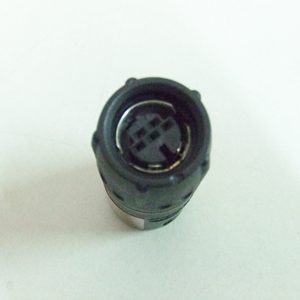
Anyway I will need it to connect the MC-2
I am looking wiring diagram socket programming MC-2
I will be grateful for your help.
I am looking wiring diagram socket programming MC-2
I will be grateful for your help.
- MC-2 socket
- MC-2.jpg (18.75 KiB) Viewed 22022 times
- zenon
- Posts: 6
- Joined: 23 Aug 2013, 12:16
- Location: Poland
Re: Q LOGIC PROGRAMMING INTERFACE
![]() by woodygb » 04 Sep 2013, 21:21
by woodygb » 04 Sep 2013, 21:21
The two larger pins will be positive and negative.
The other pin pairs will probably be.
CANBUS High & CANBUS Low
AND
Canbus High Termination & Canbus Low Termination
The other pin pairs will probably be.
CANBUS High & CANBUS Low
AND
Canbus High Termination & Canbus Low Termination
-
woodygb - Posts: 7128
- Joined: 12 Mar 2011, 18:45
- Location: Bedford UK
Re: Q LOGIC PROGRAMMING INTERFACE
![]() by falco peregrinus » 16 Sep 2013, 14:24
by falco peregrinus » 16 Sep 2013, 14:24
Hi everyone. Thanks Woody & co for the invaluable info on the Quantum. I'm keen to be gain the ability to reprogram my wife's chair - it has a Quantum controller - so I've ordered the CAN-BUS device pictured above and downloaded everything listed as required in this topic.
I'd like to be able to make up a permanent cable for the job though, rather than use a quick and dirty (albeit 100% functional) connection like is shown in the pictures above. I've spent several hours searching the internet for a plug with the two CAN-BUS pins to suit the Quantum controller, without success. Does anyone know the manufacturer and model number of a suitable plug?
Or, failing that, what I need to solder onto the end of the wires to plug into the two CAN-BUS sockets on the Quantum controller? (But I would really prefer to use a plug if I can, so that I can't possibly make a mistake and plug the CAN-BUS device into the wrong holes whilst distracted or having a lapse of concentration.)
Thanks
Falco.
-

falco peregrinus - Posts: 445
- Joined: 16 Sep 2013, 11:19
- Location: Brisbane, Australia
Re: Q LOGIC PROGRAMMING INTERFACE
![]() by woodygb » 16 Sep 2013, 14:36
by woodygb » 16 Sep 2013, 14:36
Proprietary plug .... no alternative seems to available.
-
woodygb - Posts: 7128
- Joined: 12 Mar 2011, 18:45
- Location: Bedford UK
Return to Everything Powerchair
Who is online
Users browsing this forum: Bing [Bot] and 430 guests