ex-Gooserider wrote:A lot of info you have already seen, but essentially there is no easy way to do a "universal interface", as each controller manufacturer, and often each different "model family" in a manufacturer's lineup is unique and proprietary and will only work with it's own set of related hardware. On top of this many chair manufacturers have "rebadged" versions of a given "family" and their versions might or might not work with the original factory's version, or a different chair manufacturer's version, The ONLY way that I know of to do something approaching universal is to have some sort of external mechanical device that physically moves the joystick, or to connect via one of the adapter boxes intended to allow use of 3rd party specialty controls like head arrays, sip & puff, or chin sticks.
Yes -- though that still leaves the problem of cascaded control loops. Any "solution" needs a way of leveraging the "muscle" (power module) and "user interface" (joystick controller) present in the chair's electronics but stripping it of any *smarts*. Cascading control systems that weren't intended to be cascaded inevitably leads to instability, poor performance or utter failure-of-control.
The different "families" will have different internal electronics, different hardware interconnections for cabling, different communication protocols between the different subsystems, and so on.... In addition, most of the information you would need to build an interface to any given family is more or less closely guarded proprietary info, as they REALLY don't want to see anybody actually able to make something that interfaces with their systems as that would cut into the sales of their overpriced parts... This board is one of the few where folks don't scream in horror at the very notion of someone other than a DME dealer actually working on a chair, and then only by randomly swapping out components.... (Try it over on the JunkyWheelchair board, and see what happens...)
Yes, for this (and the above) reason, I've come to the conclusion that the only "proper" solution is to replace the electronics entirely. It's more cost effective and gives the user more control over his ride. But, leaves the "naive" user without any real support.
OTOH, I have seen groups spontaneously evolve to support particular "goals". Or, some existing organization may elect to make this one of their "charitable priorities" (much as The Lions have embraced vision/blindness).
I figure the chair will be a small part of the support issues that anyone dealing with a system like mine would have to deal with. So, maybe support could develop within a community devoted to *that*!
There have been some efforts / success at hacking into the input side of the system, i.e. by opening up the joystick pod and splicing into the wiring between the joystick and the controller electronics, but that is kind of sketchy for a lot of reasons. However at least the options of what signals are present and how to tap into them are limited and fairly easy to identify...
I had thought putting a logic/protocol analyzer on the signals to/from these devices could go a long way to capturing the details of the protocol. I imagine the manufacturers DON'T try to "encrypt" their communications but, rather, rely on "security by obscurity" -- just don't TELL anyone what information is being exchanged (but, don't take pains to DISGUISE it, either!) Or, make trivial efforts to hide data (e.g., HP makes a "Secure Web Console" -- did you notice the word SECURE in that description? -- that "encrypts" the traffic that it passes down the network with a simple/trivial substitution cipher: XOR each character/byte with a particular CONSTANT! And this is "secure"???)
If so, conceivably moving the stick left, right, up, down... pressing the horn button... commanding any additional actuators, etc. and observing the data exchanged could go a long way to sorting out what is going on inside the "system".
[People have done far more with systems that were *designed* to be "secure"!]
As mentioned, I will try to pick up some additional "power modules" and "joystick controllers" so I can "sacrifice" a few. Short of deencapsulating actual components, it may be possible to tap into interfaces (e.g., JTAG) that are present to facilitate development and/or production.
I agree that it is probably easier to start from scratch for most of the control stack the way that Lenny is doing. I would consider staying with a good commercial motor controller simply because high power motor control is difficult to do well, and I think that if you avoid leaving more than controlling the basic functions to the controller box, then it shouldn't be terribly hard to switch the box if the existing product gets changed... I understand your concern about getting hosed by surpise changes on the COTS component supplier side, but there is also the tradeoff between full control of the component chain and not simply spending a lot of time reinventing the wheel...
Any vendor on which you rely leaves you vulnerable. Having to redesign *your* system simply because a vendor opted to make a change -- for whatever reason -- to *his* "component" is a terrible way to run a business (even if it's not a business, per se). Vendors seldom tell you, in advance, that a change is coming. And, may implement a change without telling you ("Gee, why do the new chairs all seem to have this problem? Have WE changed something? Let's see... no, not us! Any change notices from our suppliers??")
One firm that I worked with learned this the hard way -- a vendor of one of the software subsystems that they used suddenly decided not to sell any more licenses for version X of their software. They wanted to move customers on to version Y and eliminate support for version X -- which is understandable as The Past is often a losing investment. So, *suddenly*, they had to rewrite large portions of their codebase to adapt to the "enhancements" (changes) in version Y. And, had to relearn a whole new set of problems with their own system as customers experienced this "new" system (even though they hadn't added any new functionality of their own... anything to make their product more desireable!)
Having undertaken this effort, they were now facing the possibility (likelihood!) that it may repeat itself, again. Should they upgrade all of their "old" version X based product in the field up to the newest, version Y based? How would they deal with the inevitable introduction of version Z? <frown>
Of the various commercial systems out there, I would say the most "hacked on" here are:
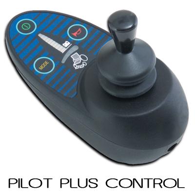
1. The Penny and Giles / P&G / PGDT "Pilot+" series,
I think that is what is present on the chair I currently rescued. The controls bear markings "PGDT".
which is what BM has used on some of his chairs, and for which the OEM level programmer has "escaped into the wild".
Where can I find this? Or, would it not benefit me?
There has been some different projects to modify their electronic innards as well - Woody has built an RC interface that talks to it, and I'm currently working out how to install a speed pot in pods that don't have one.
For the "joystick controller", I think I owuld be happy just to be able to use it as an "input device" -- and not have to repackage my own electronics to fit in that enclosure *just* to have a means of mounting the joystick in a convenient location. But, that assumes there is no "processing" of the joystick's motions within those (PGDT) electronics. Otherwise, it may be easier to just gut the box and lay out a new board that interfaces to the joystick directly.
2. The Dynamic DX series that Lenny has been using on Rachi's chair, but which needs a proprietary dongle to actually make any programming changes, however there are known places where one can purchase the dongles (though they are not cheap...)
So, there is no advantage/disadvantage to the PGDT vs. Dynamic from a typical user's point of view (unable to "program" *either* of them)
3. It is best to stay FAR away from any Pride / Quantum products, as they are probably the worst in the industry for NOT allowing access to programming tools and information. (not to mention poorer than average build quality and other issues.)
I see I will have to do more research. I had thought Pride was a reseller/dealer -- not a manufacturer. Ditto "Mobility"
From the comments, it sounds like what you have now are "in-line" style motors, which have the drive axle coming out of the motor in line with the motor shaft, and which run from side to side across the width of the chair...
Yes. In fact, the back end (cap on the brake) of one motor almost touches the back end of the other motor (there is a piece of "chassis" between them).
Usually these are seen only on the lower end chairs, (Such as the Jazzy "Select" series chairs) though there are exceptions...
Yes, from google photos, that seems to be what I have rescued (it was the smallest chair in the lot offered to me -- easiest to lift into the trunk of the car!). Most of the other chairs were VERY large -- motorized seats, etc. Stuff that wouldn't be of use to me given my desire to use it to demonstrate a concept.
What is more common, and what most of us are used to is the right-angled gear motor (what you will sometimes see described as a "Groove style" motor, where the motor has a helical gear right-angle gear box on one end so the drive axle is at right angles to the motor shaft. These motors are positioned to run alongside the frame and battery box, and usually have at least some free space around the end opposite the gear box. These motors also are almost always made with the gear box on one end, and a solenoid brake on the other, which is under a removable cap - it should be possible to put some form of encoder under the cap in addition to the brake, without significantly increasing the length of the motor.
Yes, the first chair I started to play with was a "Quickie" (?) and had drive motors like that. But, it was way too fast for me to apply in this situation (non-accessible home; "driver" who had no experience using such a chair; more of a "wheelchair" than a "powerchair"; etc.). So, I had to reevaluate how to proceed. This little chair seemed easier to manhandle into the car, less likely to bang into walls as I experimented with it (some of the larger chairs had seats that rivaled those in First Class on an airliner -- REALLY wide!). And, I was gambling might be more typically encountered among "powerchair users", in general (i.e., I'm looking for an intial solution that addresses a larger population regardless of "need")