Joystick + RC + Autonomous !...crikey
Arduino controlled wheelchair
Re: Arduino controlled wheelchair
![]() by gcebiker » 03 Aug 2015, 11:28
by gcebiker » 03 Aug 2015, 11:28
-

gcebiker - Posts: 879
- Joined: 11 Jul 2015, 14:20
- Location: Gold Coast, Queensland, Australia.
Re: Arduino controlled wheelchair
![]() by gcebiker » 04 Aug 2015, 13:40
by gcebiker » 04 Aug 2015, 13:40
Just read all of Terry2's link in the Arduino.cc forums.
Here is the post where djbs has achieved SPI communication with a wheelchair.
http://forum.arduino.cc/index.php?topic=88946.msg1164257#msg1164257
Here is the post where djbs has achieved SPI communication with a wheelchair.
http://forum.arduino.cc/index.php?topic=88946.msg1164257#msg1164257
-
gcebiker - Posts: 879
- Joined: 11 Jul 2015, 14:20
- Location: Gold Coast, Queensland, Australia.
Re: Arduino controlled wheelchair
![]() by DougL » 04 Aug 2015, 15:26
by DougL » 04 Aug 2015, 15:26
My plan is to use a standard RC Xmitter module and RX( http://hobbyking.com/hobbyking/store/__ ... II_RX.html )
An Arduino would decode the serial RX stream into the JSIG stream bytes( basically replacing the code of the wired Gravis Joystick) and then I'd use another Arduino on the TX end with the Gravis( or other ) joystick and encode it into the stream the TX module needs. Or I could use a standard RC transmitter unit and put the TX module into it.
Doug
- DougL
- Posts: 69
- Joined: 19 May 2015, 22:47
- Location: San Diego, CA USA
Re: Arduino controlled wheelchair
![]() by gcebiker » 04 Aug 2015, 15:38
by gcebiker » 04 Aug 2015, 15:38
Yeah seems like a better way to do it, tho i do like the form factor of the Wii.
The 2.4Ghz Wirless Wii Nunchuck looses sync sometimes...a bit of an issue.
Ive a whole bunch of nRF24L01+modules, so for now going to use them after i get your wired version working for my chair.
I like that the nRF24L01+'s are bi directional, it opens up the possibility of reading calibration/inhibit data on start up remotely.
-
gcebiker - Posts: 879
- Joined: 11 Jul 2015, 14:20
- Location: Gold Coast, Queensland, Australia.
Re: Arduino controlled wheelchair
![]() by DougL » 04 Aug 2015, 16:16
by DougL » 04 Aug 2015, 16:16
I want reliability with the wireless connection so going with something like RC modules is my preferred method. I too like the Nunchuck and will be using one instead of the gravis. Should be an easy swap.
The modules I linked to has a telemetry mechanism so there can be some feedback. I don't know how that would be coded yet.
Doug
The modules I linked to has a telemetry mechanism so there can be some feedback. I don't know how that would be coded yet.
Doug
- DougL
- Posts: 69
- Joined: 19 May 2015, 22:47
- Location: San Diego, CA USA
Re: Arduino controlled wheelchair
![]() by gcebiker » 05 Aug 2015, 00:11
by gcebiker » 05 Aug 2015, 00:11
Austin Davids Code i use on my wireless disabled sail boats (Access Dinghys)
RX Code , RX by nRF2401+ modules -> RC car ESC
TX Code (Transmit) Analogue Joystick from Servo City
Just sticking all the code in one place so its a bit easier to find.
- Code: Select all
 // Notes
// This sketch was tweaked to operate BRUSHED X-45 Hobby King ESC from a car.
// To operate winch motors on a disabled sailing dinghy.

// == The different limit values for the Nunchuck are deliberate.
// compensating for the ESC's 50% reduction in power when in 'reverse'
// Values from the wii nunchuck were also a little erratic in reverse,
// The if , if else , statements also helped with this.

// As this particular ESC reads neutral immediately upon start up
// and the Adruino is powered from the esc, the mapping was the only way to get neutral reliably.
// This Sketch was written for Sailability Gold Coast by Tony Matthews with
// Help from 'AustinDavid' – endless sphere forums./ Help from 'AustinDavid' – endless sphere forums.


#include <Wire.h>
#include <Servo.h>
#include <wiinunchuk.h>


Servo escnine; // Electronic Speed Controller One declaration
Servo escfive; // Electronic Speed Controller Two declaration
int neu = 128; // default zero value for X, Y axis


void setup(void)
{
  nunchuk_init();
  delay(50);
  nunchuk_calibrate_joy();

  delay(20); //wait until the esc starts in case of Arduino got power first
  escnine.attach(9, 300, 2000); // attaches the esc to digital pins and
  escfive.attach(5, 300, 2000); // sets max values and the neutral area

  delay (1000); // Arming section
  escnine.write(neu); // Write neutral value.
  delay(20);

  Serial.begin(57600);
  }

  void loop() {

  nunchuk_get_data(); // receives 6 data bytes from controller

  Serial.print("X = ");
  Serial.print(nunchuk_cjoy_x());
  Serial.print("   Y = ");
  Serial.println(nunchuk_cjoy_y());


  // Stabilize Wii output and
  // set Max values for Wii X to counter the esc 50% reduction in reverse
  if (nunchuk_cjoy_x() <= 75)
    escnine.write(75);

  else if (nunchuk_cjoy_x() >= 155)
    escnine.write(155);

  else {
    escnine.write(nunchuk_cjoy_x());
  }

  // Stabilize Wii output and
  // set Max values for Wii Y to counter the esc 50% reduction in reverse
  if (nunchuk_cjoy_y() <= 75)
    escfive.write(75);

  else if (nunchuk_cjoy_y() >= 155)
    escfive.write(155);

  else {
    escfive.write(nunchuk_cjoy_y());
  }

  delay(20); // ESCs will only change every 20ms
}


//end code
RX Code , RX by nRF2401+ modules -> RC car ESC
- Code: Select all
/*
 Written by: Mujahed Altahle

This work is licensed under the Creative Commons Attribution-NonCommercial-ShareAlike 3.0 Unported License.
To view a copy of this license, visit http://creativecommons.org/licenses/by-nc-sa/3.0/
or send a letter to Creative Commons, 444 Castro Street, Suite 900, Mountain View, California, 94041, USA.

 */
/* A simple Project for Remote Controlling with nRF24L01+ radios.
 We have 2 nodes, the transmitter (this one) and the receiver which is attached to the Car.
 The idea is to transmit  2 parameters , one is Direction (Backward, or Forward with the speed) the other is the Steering (Left, or Right with the degree of rotation).
 The nRF24L01 transmit values in type of "uint8_t" with maximum of 256 for each packet, so the values of direction is divided by (10) at the Tx side,
 then it is multiplied by 10 again at the Rx side.
 The Rx rules is to output the received parameters to port 3 and 6 where the Servo and the ESC are are attached
 a condition is required to prevent the controller from transmitting values that is not useful (like 1480-1530 for ESC and 88-92 for Servo) to save more power as much as we can
 */

#include <Servo.h>
#include <SPI.h>
#include "nRF24L01.h"
#include "RF24.h"
#include "printf.h"
//
// Hardware configuration
//

// Set up nRF24L01 radio on SPI bus plus pins 9 & 10
RF24 radio(9,10);

Servo servo; //steering servo declaration
Servo esc; // Electronic Speed Contoller declaration

// Single radio pipe address for the 2 nodes to communicate.
const uint64_t pipe = 0xE8E8F0F0E1LL;

//
// Payload
//

uint8_t received_data[2];
uint8_t num_received_data =sizeof(received_data);

//
// Setup
//

void setup(void)
{
  delay(3000); //wait until the esc starts in case of Arduino got power first
  servo.attach(3);  // attaches the servo on pin 3 to the servo object
  esc.attach(6);  // attaches the ESC on pin 6 to the ese object
  servo.write(90);
  //
  // Print preamble
  //

  Serial.begin(57600);
  printf_begin();

  //
  // Setup and configure rf radio
  //

  radio.begin(); //Begin operation of the chip.
  // This simple sketch opens a single pipes for these two nodes to communicate
  // back and forth.  One listens on it, the other talks to it.
  radio.openReadingPipe(1,pipe);
  radio.startListening();
  //
  // Dump the configuration of the rf unit for debugging
  //
  radio.printDetails();
}


void loop(void)
{
  // if there is data ready
  if ( radio.available() )
  {
    bool done = false;
    int ESC_value;
    while (!done)
    {
      // Fetch the payload, and see if this was the last one.
      done = radio.read( received_data, num_received_data );
      ESC_value=received_data[0]*10; //Multiplication by 10 because the ESC operates for vlues around 1500 and the nRF24L01 can transmit maximum of 255 per packet
      esc.writeMicroseconds(ESC_value);
    //  Serial.println(ESC_value);
      servo.write((received_data[1]));
     // Serial.println(received_data[1]);
    }
  }
}
TX Code (Transmit) Analogue Joystick from Servo City
- Code: Select all
/*
Written by: Mujahed Altahle
This work is licensed under the Creative Commons Attribution-NonCommercial-ShareAlike 3.0 Unported License.
To view a copy of this license, visit http://creativecommons.org/licenses/by-nc-sa/3.0/
or send a letter to Creative Commons, 444 Castro Street, Suite 900, Mountain View, California, 94041, USA.
*/

/* A simple Project for Remote Controlling with nRF24L01+ radios.
We have 2 nodes, the transmitter (this one) and the receiver which is attached to the Car.
The idea is to transmit 2 parameters , one is Direction (Backward, or Forward with the speed) the other is the Steering (Left, or Right with the degree of rotation).
The nRF24L01 transmit values in type of "uint8_t" with maximum of 256 for each packet, so the values of direction is divided by (10) at the Tx side,
then it is multiplied by 10 again at the Rx side.
The Rx rules is to output the received parameters to port 3 and 6 where the Servo and the ESC are are attached
a condition is required to prevent the controller from transmitting values that is not useful (like 1480-1530 for ESC and 88-92 for Servo) to save more power as much as we can
*/
#include <SPI.h>
#include "nRF24L01.h"
#include "RF24.h"
#include "printf.h"
//
// Hardware configuration
//
// Set up nRF24L01 radio on SPI bus plus pins 9 & 10
RF24 radio(9,10);

uint8_t data[2] ; //buffer to store received data
const uint8_t buffer_size = sizeof(data);
//pins that used for the Joystick
const int analogInPinY= A0; //
const int analogInPinX = A1;//
const int tx_led=2;// transmission indicator
int Y_value = 0; // values read from the pot
int X_value = 0;
int outputValue = 0;
/*
const int transmit_pin=6;
int transmit_enable;
int ForwrdButton=2;
int BackwrdButton=3;
*/
//
// Topology
//

// Single radio pipe address for the 2 nodes to communicate.
const uint64_t pipe = 0xE8E8F0F0E1LL;


//
// Setup
//

void setup(void)
{

  Serial.begin(57600);
  printf_begin();

  //
  // Setup and configure rf radio
  //

  radio.begin();

  radio.openWritingPipe(pipe);
  //
  // Dump the configuration of the rf unit for debugging
  //

  radio.printDetails();

  //
  // Set up buttons
  //

  /*to be used later
pinMode(ForwrdButton,INPUT );
pinMode(BackwrdButton,INPUT);
pinMode(transmit_enable,INPUT);
*/
  pinMode(tx_led,OUTPUT);
  digitalWrite(tx_led,LOW);

}

//
// Loop
//

void loop(void)
{

  X_value = analogRead(analogInPinX);
  data[0] = map(X_value, 0, 1023,100 , 200);
  Y_value = analogRead(analogInPinY);
  data[1] = map(Y_value, 0, 1023, 135, 45);
// transmit_enable=!digitalRead(transmit_pin);
  //an error ratio around +3,-3 appears coming from the Joystick all the time,
  //so we neglect them (using the following if statement) because they make the system transmitting data always and they are useless and waste of power
  if((data[0]>153 || data[0] <=149) || (data[1]>=92 || data[1]<88))
  {
    //printf("Now sending...");
    bool ok = radio.write( data, buffer_size );
    //if (ok)
    printf("ok\n\r");
    // else
    printf("failed\n\r");
    // delay(15);
    digitalWrite(tx_led,HIGH); //turn led on after transmission
  }
  else digitalWrite(tx_led,LOW);//keep led off when no transmission
}
Just sticking all the code in one place so its a bit easier to find.
-
gcebiker - Posts: 879
- Joined: 11 Jul 2015, 14:20
- Location: Gold Coast, Queensland, Australia.
Re: Arduino controlled wheelchair
![]() by gcebiker » 05 Aug 2015, 00:46
by gcebiker » 05 Aug 2015, 00:46
Cant plug the Arduino directly into the XLR connector...28.8v 
I've a Wizard Cable for the DX, i guess it has a Logic Level Converter so the High volts at the XLR charging port dont fry the USB ports on your PC ?
Doug how did you connect your Gravis/Arduino to the XLR, a LLC ?
Ive a bunch of JST Balance leads (for balance charging RC LiPo batteries), will investigate soldering directly to board.
Its my hope that eventually there will be a bunch of 'include' files for Arduino library, one for each type of controller as they come along.
-
gcebiker - Posts: 879
- Joined: 11 Jul 2015, 14:20
- Location: Gold Coast, Queensland, Australia.
Re: Arduino controlled wheelchair
![]() by gcebiker » 05 Aug 2015, 03:24
by gcebiker » 05 Aug 2015, 03:24
Internals for Wii Nunchuck wired version.
Top to bottom wiring, is Gnd, SDA,SCL,VDD.
Im not sure how to resize it for the forum so link to it here
Top to bottom wiring, is Gnd, SDA,SCL,VDD.
Im not sure how to resize it for the forum so link to it here
-
gcebiker - Posts: 879
- Joined: 11 Jul 2015, 14:20
- Location: Gold Coast, Queensland, Australia.
Re: Arduino controlled wheelchair
![]() by DougL » 05 Aug 2015, 03:32
by DougL » 05 Aug 2015, 03:32
gcebiker wrote:Cant plug the Arduino directly into the XLR connector...28.8v
I've a Wizard Cable for the DX, i guess it has a Logic Level Converter so the High volts at the XLR charging port dont fry the USB ports on your PC ?
Doug how did you connect your Gravis/Arduino to the XLR, a LLC ?
Ive a bunch of JST Balance leads (for balance charging RC LiPo batteries), will investigate soldering directly to board.
Its my hope that eventually there will be a bunch of 'include' files for Arduino library, one for each type of controller as they come along.
I use an adjustable DC-DC converter which is good to over 30V on input to give me 5V for the arduino and Gravis POT pullup. And remember, I'm currently connecting without the joystick so I have an inline 4 pin pigtail from the powerbase to connect to. That was 3D printed by someone at the fablab I hang out at. Best/easiest is to use those cheap Amazon or eBay DC-DC converters to take the 28V to 5V.
Doug
- DougL
- Posts: 69
- Joined: 19 May 2015, 22:47
- Location: San Diego, CA USA
Re: Arduino controlled wheelchair
![]() by gcebiker » 05 Aug 2015, 12:29
by gcebiker » 05 Aug 2015, 12:29
Took the Dynamic controls apart, Found Data lines did not go to the Power jack, they must be the RX TX ?
Soldered in a four Pin JST balance lead so the Arduino can be connected and disconnected for testing.
Went looking for a 5v source that was available when the Chairs Joystick is turned off.
Non before the On/Off switch...On/Off switch uses full battery Voltage so for now will run Arduino from Single cell LiPo.
Data Lines Purple, Yellow - Writing on Board "SPR Bus"


The Black Capacitor near the Voltage regulator , bottom of pic.
Is the one that wears out and causes the Brakes to engage/disengage when chair is first turned on till it warms up...when you are just sitting there, its a but unnerving.

No Pads on bottom of this for data , i spliced into the Yellow/Blue shown in previous pictures.


Lead pokes out bottom of Jazzy Joystick. Ill Velcro a holder for a Single Cell LiPO to hold battery during testing.

Soldered in a four Pin JST balance lead so the Arduino can be connected and disconnected for testing.
Went looking for a 5v source that was available when the Chairs Joystick is turned off.
Non before the On/Off switch...On/Off switch uses full battery Voltage so for now will run Arduino from Single cell LiPo.
Data Lines Purple, Yellow - Writing on Board "SPR Bus"
The Black Capacitor near the Voltage regulator , bottom of pic.
Is the one that wears out and causes the Brakes to engage/disengage when chair is first turned on till it warms up...when you are just sitting there, its a but unnerving.
No Pads on bottom of this for data , i spliced into the Yellow/Blue shown in previous pictures.
Lead pokes out bottom of Jazzy Joystick. Ill Velcro a holder for a Single Cell LiPO to hold battery during testing.
-
gcebiker - Posts: 879
- Joined: 11 Jul 2015, 14:20
- Location: Gold Coast, Queensland, Australia.
Re: Arduino controlled wheelchair
![]() by gcebiker » 07 Aug 2015, 10:24
by gcebiker » 07 Aug 2015, 10:24
Ordered some Buck converters,
Arduino on breadboard(Single Cell LiPo, Gnd and Vin), Spark Fun Pot (Analogue Pin 0, 5v and ground), Momentary switch (Digital Pin 4)
Two Data Lines, Pin TX and 11 to chair, its communicating (affects lights on original joystick)
Maybe i need ground and + connected too ? or just ground ?
I also hope (if i can get this first one going) to put some ultrasonic sensors on another powerchair/Arduino to help some mates with brain injuries get about+
...with out taking out the skirting boards all around the house.
-
gcebiker - Posts: 879
- Joined: 11 Jul 2015, 14:20
- Location: Gold Coast, Queensland, Australia.
Re: Arduino controlled wheelchair
![]() by Burgerman » 07 Aug 2015, 10:40
by Burgerman » 07 Aug 2015, 10:40
I also hope (if i can get this first one going) to put some ultrasonic sensors on another powerchair/Arduino to help some mates with brain injuries get about+
...with out taking out the skirting boards all around the house.
You will need to remove all the steer acc delay, and steer deceleration delay from the controllers too. Via programming, because your skirting boards and door frames will still suffer. They can continue to turn for about 1.5 seconds AFTER you zero or add opposite stick.
-

Burgerman - Site Admin
- Posts: 70988
- Joined: 27 May 2008, 21:24
- Location: United Kingdom
Re: Arduino controlled wheelchair
![]() by gcebiker » 07 Aug 2015, 12:21
by gcebiker » 07 Aug 2015, 12:21
Ah found the info over on the Arduino.cc site, i need a ground shared.
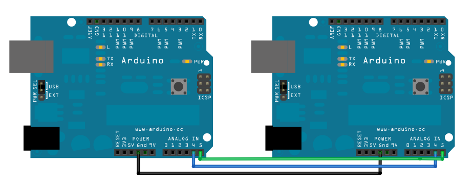
Ok , I am using an Arduino Nano V3.0 so pins are different (plus its codded differently) but the info applies re.grounding.
Connect pin 5 (the clock, or SCL, pin) and pin 4 (the data, or SDA, pin) on the master Arduino to their counterparts on the slave board. Make sure that both boards share a common ground. In order to enable serial communication, the slave Arduino must be connected to your computer via USB.
Ok , I am using an Arduino Nano V3.0 so pins are different (plus its codded differently) but the info applies re.grounding.
-
gcebiker - Posts: 879
- Joined: 11 Jul 2015, 14:20
- Location: Gold Coast, Queensland, Australia.
Re: Arduino controlled wheelchair
![]() by gcebiker » 09 Aug 2015, 14:13
by gcebiker » 09 Aug 2015, 14:13
Hooked up ground to Arduino today,
Gnd from charge port.
Digital 11 SDA/MOSI to Arduino Pin 11 (Yellow wire)
Digital 13 SCL/SCK to Arduino Pin 13 (Blue wire)
Compiled with Arduino 1.0.5
Nothin happening as yet,
Maybe i need to wait for my DC-DC converter and hook up the + ?
Maybe i am compiling with wrong version of Arduino IDE ?
..Bus Pirate should be here soon and i can at least compare output of Arduino to Output from Jazzy Joystick.
Picture of test rig so far, just one input and one inhibit button so far.

Am i on the right track Doug ?
Gnd from charge port.
Digital 11 SDA/MOSI to Arduino Pin 11 (Yellow wire)
Digital 13 SCL/SCK to Arduino Pin 13 (Blue wire)
Compiled with Arduino 1.0.5
Nothin happening as yet,
Maybe i need to wait for my DC-DC converter and hook up the + ?
Maybe i am compiling with wrong version of Arduino IDE ?
..Bus Pirate should be here soon and i can at least compare output of Arduino to Output from Jazzy Joystick.
Picture of test rig so far, just one input and one inhibit button so far.
Am i on the right track Doug ?
-
gcebiker - Posts: 879
- Joined: 11 Jul 2015, 14:20
- Location: Gold Coast, Queensland, Australia.
Re: Arduino controlled wheelchair
![]() by DougL » 09 Aug 2015, 15:25
by DougL » 09 Aug 2015, 15:25
There is no need to connect the 28V to your control rig, you just need the ground to make sure the signal levels of the Arduino controller are referenced from the same point as the power base controller.
As for it not doing anything, it's tough to say, can you read the code(and know what it's doing)? One thing I know you'd want to do is zero the joy stick you have connected. Then you'd want to trigger the initialization sequence to be run. IIRC, the LED is a joystick centering indicator so you should be seeing that LED going on/off when you move the joystick off of center and then back to center. And if your joystick does not go back to exactly the same spot, you might have to change the Zero'ing offset value. I think it was set to 10 for the Gravis stick which seemed to be off by around 5-7 through various tests of moving the stick and then releasing it and watching where it centers.
You are going to want more than one button, if I read your reply correctly you stated you only have one button implemented.... The code lists the buttons and the pins I used for those buttons.
Another thing I noticed was you don't seem to have the TX line connected and I don't know why you wouldn't do that since it is how the whole thing works, ie sends a serial byte stream to the power base controller.
Doug
- DougL
- Posts: 69
- Joined: 19 May 2015, 22:47
- Location: San Diego, CA USA
Re: Arduino controlled wheelchair
![]() by gcebiker » 09 Aug 2015, 15:45
by gcebiker » 09 Aug 2015, 15:45
There is no need to connect the 28V to your control rig, you just need the ground to make sure the signal levels of the Arduino controller are referenced from the same point as the power base controller.
Cool got that bit right.
As for it not doing anything, it's tough to say, can you read the code(and know what it's doing)? One thing I know you'd want to do is zero the joy stick you have connected. Then you'd want to trigger the initialization sequence to be run. IIRC, the LED is a joystick centering indicator so you should be seeing that LED going on/off when you move the joystick off of center and then back to center. And if your joystick does not go back to exactly the same spot, you might have to change the Zero'ing offset value. I think it was set to 10 for the Gravis stick which seemed to be off by around 5-7 through various tests of moving the stick and then releasing it and watching where it centers.
Chairs not moving but i can see it writing data on the serial monitor port of the IDE (sometimes i power it from there instead of the battery). Ill change to a larger Joystick , this ones just to tiny to be accurate in all likely hood.
I am ok with the code, as you have great notes, just was not sure which Digital pins were witch.
You are going to want more than one button, if I read your reply correctly you stated you only have one button implemented.... The code lists the buttons and the pins I used for those buttons.
One Joystick just for now while i am in testing.
Another thing I noticed was you don't seem to have the TX line connected and I don't know why you wouldn't do that since it is how the whole thing works, ie sends a serial byte stream to the power base controller.
Oh, i originally had it hooked up, Digital 11 and TX but thought i read the code wrong and switched it to D11 and D13
I'll be switching my input joystick over to a full size wheelchair joy with much stronger springs and seeing how it goes re:center values.
-
gcebiker - Posts: 879
- Joined: 11 Jul 2015, 14:20
- Location: Gold Coast, Queensland, Australia.
Re: Arduino controlled wheelchair
![]() by gcebiker » 09 Aug 2015, 15:57
by gcebiker » 09 Aug 2015, 15:57
Ive a Jazzy 600 joy , quite possibly its sending different messages.
Ill know more when the sniffer gets here, should not be to far away.
Post from the USA to Australia is pretty fast.
Ill know more when the sniffer gets here, should not be to far away.
Post from the USA to Australia is pretty fast.
-
gcebiker - Posts: 879
- Joined: 11 Jul 2015, 14:20
- Location: Gold Coast, Queensland, Australia.
Re: Arduino controlled wheelchair
![]() by gcebiker » 09 Aug 2015, 16:15
by gcebiker » 09 Aug 2015, 16:15
It all seems ok, ill check again in the morning..1am here i better at least try to get some sleep.
Screen dump of short , power up, press on button, run, press off button.
Start DEBUG
Power Off
LED Indicator - !inhibit
****drive=(0)****turn=(0)****throttle=(4)
LED Indicator - !inhibit
****drive=(0)****turn=(-12)****throttle=(4)
LED Indicator - !inhibit
****drive=(0)****turn=(-12)****throttle=(4)
LED Indicator - !inhibit
****drive=(0)****turn=(0)****throttle=(4)
PALM Button Toggle
Power Off
Random turn value sneaking in (joystick not being touched) ....mmm, ill make adjustments tomorrow.
-
gcebiker - Posts: 879
- Joined: 11 Jul 2015, 14:20
- Location: Gold Coast, Queensland, Australia.
Re: Arduino controlled wheelchair
![]() by DougL » 09 Aug 2015, 17:46
by DougL » 09 Aug 2015, 17:46
SOB.... I just spent 45 minutes commenting item by item referencing my code to be specific etc and finally hit preview and the forum made me log back and it dumped all my comments... crap...
FYI, what I did is for the Jazzy Select and the mode of joystick it uses. That joystick is very different from the Jazzy 600 so don't expect it to work. And I suggest you draw out a flow chart on how the code works so you understand why I mentioned using/having buttons. It does not matter if you have 10 joysticks, you need the 4 buttons if you try to use my code without any customizations for your configuration. Also, you can't use the TX line to control the chair base and have it outputting to a terminal window for debugging.
Doug
gcebiker wrote:There is no need to connect the 28V to your control rig, you just need the ground to make sure the signal levels of the Arduino controller are referenced from the same point as the power base controller.
Cool got that bit right.As for it not doing anything, it's tough to say, can you read the code(and know what it's doing)? One thing I know you'd want to do is zero the joy stick you have connected. Then you'd want to trigger the initialization sequence to be run. IIRC, the LED is a joystick centering indicator so you should be seeing that LED going on/off when you move the joystick off of center and then back to center. And if your joystick does not go back to exactly the same spot, you might have to change the Zero'ing offset value. I think it was set to 10 for the Gravis stick which seemed to be off by around 5-7 through various tests of moving the stick and then releasing it and watching where it centers.
Chairs not moving but i can see it writing data on the serial monitor port of the IDE (sometimes i power it from there instead of the battery). Ill change to a larger Joystick , this ones just to tiny to be accurate in all likely hood.
I am ok with the code, as you have great notes, just was not sure which Digital pins were witch.You are going to want more than one button, if I read your reply correctly you stated you only have one button implemented.... The code lists the buttons and the pins I used for those buttons.
One Joystick just for now while i am in testing.Another thing I noticed was you don't seem to have the TX line connected and I don't know why you wouldn't do that since it is how the whole thing works, ie sends a serial byte stream to the power base controller.
Oh, i originally had it hooked up, Digital 11 and TX but thought i read the code wrong and switched it to D11 and D13
I'll be switching my input joystick over to a full size wheelchair joy with much stronger springs and seeing how it goes re:center values.
- DougL
- Posts: 69
- Joined: 19 May 2015, 22:47
- Location: San Diego, CA USA
Re: Arduino controlled wheelchair
![]() by Burgerman » 09 Aug 2015, 18:34
by Burgerman » 09 Aug 2015, 18:34
SOB.... I just spent 45 minutes commenting item by item referencing my code to be specific etc and finally hit preview and the forum made me log back and it dumped all my comments... crap...
Depends on browser. With most just click back. "Copy" log in, then "paste"...
-
Burgerman - Site Admin
- Posts: 70988
- Joined: 27 May 2008, 21:24
- Location: United Kingdom
Re: Arduino controlled wheelchair
![]() by DougL » 09 Aug 2015, 20:00
by DougL » 09 Aug 2015, 20:00
Burgerman wrote:SOB.... I just spent 45 minutes commenting item by item referencing my code to be specific etc and finally hit preview and the forum made me log back and it dumped all my comments... crap...
Depends on browser. With most just click back. "Copy" log in, then "paste"...
yes, I did use the back button but never saw any indicator to repost the data or anything, just the original msg. I'm using Chrome. From now on, if the reply is long then I will open another window to be sure I'm still logged in and haven't timed out.
Maybe the issue was with my hitting the Preview option instead of Submit. I'd mucked with lots of quote/unquoting so wanted to see if I missed anything before submitting.
- DougL
- Posts: 69
- Joined: 19 May 2015, 22:47
- Location: San Diego, CA USA
Re: Arduino controlled wheelchair
![]() by DougL » 09 Aug 2015, 20:06
by DougL » 09 Aug 2015, 20:06
Regarding the Wii Nunchuck, I found the Wiichuck library and fixed it to work with the Arduino IDE I'm using 1.6.4 and I wrote an example sketch to test it using an Adafruit Trinket Pro 3V. It's working fine. My next test is to see if it really does work with the 5V version as many said it would. You see, the Wii Nunchuck is a 3.3v part but I know from sniffing the Jazzy Select joystick that it requires 5V logic so instead of going through the effort of a level shifter just for 3.3V I2C for the Wii Nunchuck I'm going to give the 5V a shot.
ok, the 5V Trinket Pro works with the Wii Nunchuck. I'll work on cleaning up the code to handle either joystick. Boy, time to get my blog on this going and get into getting my git repository going to post the code since my blog won't let me post/store zip files.
ok, the 5V Trinket Pro works with the Wii Nunchuck. I'll work on cleaning up the code to handle either joystick. Boy, time to get my blog on this going and get into getting my git repository going to post the code since my blog won't let me post/store zip files.
- DougL
- Posts: 69
- Joined: 19 May 2015, 22:47
- Location: San Diego, CA USA
Re: Arduino controlled wheelchair
![]() by gcebiker » 10 Aug 2015, 02:50
by gcebiker » 10 Aug 2015, 02:50
Changed from pro-type to break out board for testing.
Break out board runs from 12v wall power supply.
Joystick now outputting correctly (A0, A1 values were being affected by lack of power from single cell LiPo)
Ive not implemented wiring for other three Digital inputs in code as the Nano V 3.0 has internal PullUp resistors.
Tested in Debug Serial monitor mode to confirm this.
(i just moved the D4 Plug along to test a 'button press' for D3, D10, D12 )
/Thank you for reminder to re- comment out the first line in code...i'd forgotten to do that this morning at 1am...a bit sleepy
Awaiting Bus Pirate so i can sniff the Jazzy 600 data.
Ive also a brand new Q-Logic Joystick and controller in shed (was in my Q6 Edge, retro fitted with the Jazzy 600 Joy)
Q-Logic Joy always putting me into side of doorways when going up ramps, same old problem...to much input lag programed in.
I'll sniff that too, just to see what is happening.
Picture of my current break out board wiring.
-
gcebiker - Posts: 879
- Joined: 11 Jul 2015, 14:20
- Location: Gold Coast, Queensland, Australia.
Re: Arduino controlled wheelchair
![]() by gcebiker » 10 Aug 2015, 05:35
by gcebiker » 10 Aug 2015, 05:35
Ill be working on code later tonight but here is pro-type boards connected up.
Wii 2.4ghz wireless - Wii Dongle - Nano to convert wii to analogue & Digital out - Nano convert analog/digital in to, Power chair out.
Hopefully i can get it all sorted that its stack-able like a shield.

Wii 2.4ghz wireless - Wii Dongle - Nano to convert wii to analogue & Digital out - Nano convert analog/digital in to, Power chair out.
Hopefully i can get it all sorted that its stack-able like a shield.
-
gcebiker - Posts: 879
- Joined: 11 Jul 2015, 14:20
- Location: Gold Coast, Queensland, Australia.
Re: Arduino controlled wheelchair
![]() by DougL » 10 Aug 2015, 05:50
by DougL » 10 Aug 2015, 05:50
looks good and with the Nunchuck/Nano outputting PWM I'm guessing that's in preparations for a Transmitter/Receiver long range wireless setup?
I connected up and coded up the Wii Nunchuck today so now it's changing a #define and commenting out a few #includes to swap between Gravis control or Wii Nunchuck control. For the Nunchuck and it's 2 buttons I currently use one for power On/Off and the other for doing a center calibration. For Throttle, I use the X axis rotation with clockwise increasing speed and when going over center and counter clockwise it'll decrease speed.
As for the wireless Wii Nunchuck, do you know what that range is? if the range is good enough for the chair up the ramp and you at the dock you'll almost done. Implementing a knock-knock method to unlock the system so that anyone who sees you with a Wii Nunchuck won't try to screw with you using their own.
The plan looks good and now it's just figuring out what's going on with the Jazzy 600 joystick protocol.
- DougL
- Posts: 69
- Joined: 19 May 2015, 22:47
- Location: San Diego, CA USA
Re: Arduino controlled wheelchair
![]() by gcebiker » 10 Aug 2015, 06:42
by gcebiker » 10 Aug 2015, 06:42
Range on the Wii as it comes is not very good....dont need much standing in front of the gaming console.
The Wii Nunchuck wireless only has a PCB track antenna's, a better circular polarized antenna on RX and TX should improve things considerably.
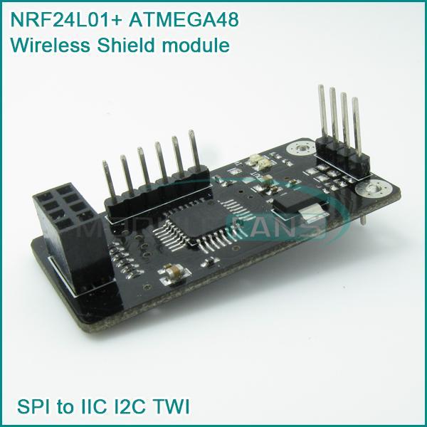
Failing that i will use the Spark fun joy in a Jiffy box with an Arduino Nano and NRF2401+ as Transmitter.
Nano + NRF2401+ receiver to Analog
Nano analog to Power chair.
Long term i wont be leaving my good house chair anywhere unattended, its just part of the testing phase.
I'll lead up to a dedicated power chair base that i use outside semi permanently attached to a Custom made Trailer to take a PolyCraft Tough Tender boat.
Local creek is two blocks from my house with direct access to the Gold Coast Broadwater for fishing.
The Wii Nunchuck wireless only has a PCB track antenna's, a better circular polarized antenna on RX and TX should improve things considerably.
Failing that i will use the Spark fun joy in a Jiffy box with an Arduino Nano and NRF2401+ as Transmitter.
Nano + NRF2401+ receiver to Analog
Nano analog to Power chair.
Long term i wont be leaving my good house chair anywhere unattended, its just part of the testing phase.
I'll lead up to a dedicated power chair base that i use outside semi permanently attached to a Custom made Trailer to take a PolyCraft Tough Tender boat.
Local creek is two blocks from my house with direct access to the Gold Coast Broadwater for fishing.
-
gcebiker - Posts: 879
- Joined: 11 Jul 2015, 14:20
- Location: Gold Coast, Queensland, Australia.
Re: Arduino controlled wheelchair
![]() by ex-Gooserider » 11 Aug 2015, 04:17
by ex-Gooserider » 11 Aug 2015, 04:17
I don't know if it's available for Chrome, but an addin that I have for Firefox called 'Lazarus' is a real life-saver in situations like this... Essentially it saves anything you put in a form for the last several entries, and allows easy one click recovery of lost info... Doesn't work on everything, partly because of the cute tricks that some places use, but it's almost always things that you really don't want to have recoverable, like passwords, credit card numbers and so on.... Very highly recommended!....
ex-Gooserider
ex-Gooserider
DougL wrote:Burgerman wrote:SOB.... I just spent 45 minutes commenting item by item referencing my code to be specific etc and finally hit preview and the forum made me log back and it dumped all my comments... crap...
Depends on browser. With most just click back. "Copy" log in, then "paste"...
yes, I did use the back button but never saw any indicator to repost the data or anything, just the original msg. I'm using Chrome. From now on, if the reply is long then I will open another window to be sure I'm still logged in and haven't timed out.
Maybe the issue was with my hitting the Preview option instead of Submit. I'd mucked with lots of quote/unquoting so wanted to see if I missed anything before submitting.
-

ex-Gooserider - Posts: 6232
- Joined: 15 Feb 2011, 06:17
- Location: Billerica, MA. USA
Re: Arduino controlled wheelchair
![]() by DougL » 11 Aug 2015, 04:31
by DougL » 11 Aug 2015, 04:31
ex-Gooserider wrote:I don't know if it's available for Chrome, but an addin that I have for Firefox called 'Lazarus' is a real life-saver in situations like this... Essentially it saves anything you put in a form for the last several entries, and allows easy one click recovery of lost info... Doesn't work on everything, partly because of the cute tricks that some places use, but it's almost always things that you really don't want to have recoverable, like passwords, credit card numbers and so on.... Very highly recommended!....
ex-Gooserider
It is available for chrome and it's been added. thanks.
Doug
- DougL
- Posts: 69
- Joined: 19 May 2015, 22:47
- Location: San Diego, CA USA
Re: Arduino controlled wheelchair
![]() by gcebiker » 12 Aug 2015, 09:05
by gcebiker » 12 Aug 2015, 09:05
A work in progress..
I know ill need a different .h library as the current one has no Joystick button implemented to save coding space but i would like to use it as the on/off button.
Code for Wii Remote I2C data (can also be used for wired Wii Joystick)
Analog Output for DougL Jazzy (forget the model)
New Arduino boards in the mail from AliExpress...maybe can do away with two Arduinos on receiver end... /fingers crossed.
Maybe ill also be able to use the NRF2401+ on both ends to get better range, even if i have to bust open the nunchuck case and stuff it inside... .
http://www.aliexpress.com/store/product ... 78020.html
- Code: Select all
// Wii Nunchuck 2.4ghz wireless to PWM out on pins 3,6. Digital to D4
// will need different wiinunchuck library for middle joy button for on off.
// intent, Joy button = on off, Joy xy = pwm output for second arduino
// Joy C = Speed up, Joy Z = speed down
// Outputs at testing show second arduino with swinging values
// may need to add some hardware or software smoothing of values or sending data differently

#include <Wire.h>

#include <wiinunchuk.h>


// Map and name pins
const int analogOutPin3 = 3 ; // PWM output value from wii Receiver
const int analogOutPin6 = 6 ; // PWM output value from Wii Receiver
const int digitalOutPin4 = 4 ; // Digital On/Off from Wii Joy thumbstick button.

int outputValue3 = 0;
int outputValue6 = 0;

void setup(void)
{
  nunchuk_init();
  delay(50);
  nunchuk_calibrate_joy();

  //delay(20); //wait until the not Arduino's get power ? Maybe not necessary


  Serial.begin(57600);
  }

  void loop() {

  nunchuk_get_data(); // receives 6 data bytes from controller
  outputValue3  = map(nunchuk_cjoy_x(),0,1023,0,255);
  outputValue6  = map(nunchuk_cjoy_y(),0,1023,0,255);
  //  finish this on/of line // outputValueD4 =  (nunchuck_cjoy_


  // Write Wii Data to appropriate Output port
  analogWrite(analogOutPin3,outputValue3);
  analogWrite(analogOutPin6,outputValue6);
  //digital write Boolean for on off value, note to self complete this line.

  // Print Debug Data to Serial Monitor
  Serial.print("X = ");
  Serial.print(nunchuk_cjoy_x());
  Serial.print("  ,  A3 Output = ");
  Serial.print(outputValue3);

  Serial.print("  ||  Y = ");
  Serial.print(nunchuk_cjoy_y());
  Serial.print("  ,  A6 Output= ");
  Serial.println(outputValue6);

  }
-
gcebiker - Posts: 879
- Joined: 11 Jul 2015, 14:20
- Location: Gold Coast, Queensland, Australia.
Re: Arduino controlled wheelchair
![]() by gcebiker » 12 Aug 2015, 09:45
by gcebiker » 12 Aug 2015, 09:45
Bugger, seems like that's just a shield for the RF24, i thought it was stand alone arduino board...no wonder i could not find any Analog or Digital in/outs.../doh
Silly me.
Silly me.
-
gcebiker - Posts: 879
- Joined: 11 Jul 2015, 14:20
- Location: Gold Coast, Queensland, Australia.
Return to Everything Powerchair
Who is online
Users browsing this forum: Bing [Bot] and 950 guests