LROBBINS wrote:A large MOSFET is one kind of power transistor. They are most often used these days for motor controller because they have very low resistance in the ON state, so lose little power as heat. The physics and circuit design for a MOSFET is quite different from that for a bipolar transistor and there are advantages and disadvantages to each e.g if you want to make an amplifier, a bipolar is easier use, if you want just ON/OFF a mosfet is more efficient.
Thankyou for that. Is a bipolar transistor what is commonly thought of a conventional 'tansistor'? Aka one of these: (see attached sketch).
 Viewed 4476 times")
Burgerman wrote:I think a bit of clarification of how the controller controls the motor is in order first so that it can be undrstood what on / off means.
The mosfet is a on off switch. There is a bunch of them but for the sake of explanation we only need consider one. The battery power is fed in at one side. And taken out of the other to the motor. The mosfet is turned on and off at a high speed (just above audio frequency so you cant hear its affect on the motor). This is a fixed frequency and happens all the time the motor controller is turned on.
The length of time the Mosfet is turned on depends on how much power you want. So when stationary, you have it turned on 0% of the time.
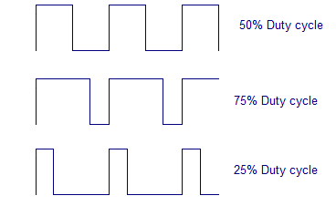
At half speed, you have it switched on for 50 percent of the time. Thats a 50% pulsewidth. So its the FULL 24V battery voltage for half of the time, and NO battery voltage for half of the time, continually at high frequency. The AVERAGE voltage is then half battery voltage. An occiloscope will show a 24v square wave pulse.
Like this:
Thankyou I understand now. The large 415v ac 3ph squirrel cage motors where I used to work were controlled in a similar way. They used diodes to convert the ac to dc, then chopped the dc up into a square ware using thyristors. I assume thyristors can cope with alternating current? But I don't know very much about electronics.
Back to my scooter, would you be able to explain to me how the braking and downhill speed regualting works? For what I've learnt is there's an electro/mech brake on the side of the motor which acts like a handbrake. This is what I hear clicking on powering up/off and when coming to a halt when riding. It acts like a handbrake or auto hold system in an automatic car?
But regarding say speed regulating when going downhill. There's a long downhill section I sometimes go down, cylists reach about 40mph+. Anyway while trundling down the hill I've often thought of stopping at the top, disengaging the drive, and freewheeling down the hill while controlling the speed on the single rear mechanical disc brake the scooter has. see attached photos. (brake lever is top left of tiller). But I don't believe it'd work because I seem to remember reading somewhere that the scooter still regulated the top speed even in freewheel motion?
So this brings me back to the question, please could you explain how the downhill speed is regulated both when in drive, and (out of drive) if possible? It's not that I want to disengage the drive and freewheel down the hill becuase I'm not too sure how efficient the disc brake is and I'm not in any fit physical state to bail out into the bushes!

Also why is there more than one MOSFET? Is it to do with needing additional switching to be able to put the motor into reverse? and also deliver different speed commands to the LH and RH drive wheels on powerchairs, and also the tilt mechanism?
Sorry for all the questions but I like learing new things as long as they're not too complicated!


