download/file.php?id=4850&mode=view these are fine, as long as they are soldered.
download/file.php?id=4851&mode=view Only 0 and 8 here need connecting with the heavy cable. All the rest, 1,2,3,4,5,6,7 can be connected with thin balance wire if you want. SOLDERED!
S646se - Full LITHIUM Pack Project - First Attempt
Re: S646se - Full Pack Project - First Attempt
![]() by Burgerman » 10 Apr 2016, 22:50
by Burgerman » 10 Apr 2016, 22:50
-

Burgerman - Site Admin
- Posts: 69927
- Joined: 27 May 2008, 21:24
- Location: United Kingdom
Re: S646se - Full Pack Project - First Attempt
![]() by LROBBINS » 10 Apr 2016, 22:59
by LROBBINS » 10 Apr 2016, 22:59
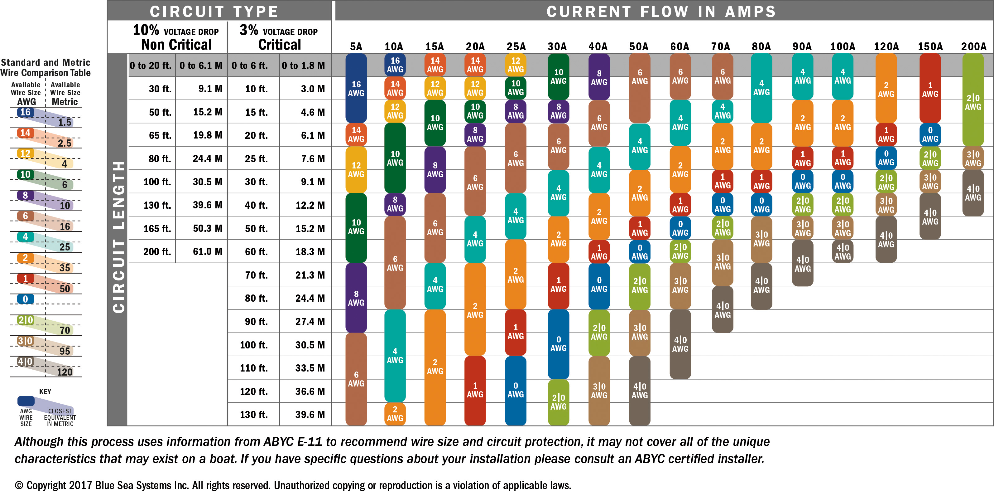
Here's a link to one of many sites with tables comparing AWG and metric wire sizes: http://www.technick.net/public/code/cp_dpage.php?aiocp_dp=guide_awg_to_metric AWG8 is 8.36 mm2, hence even larger than the 6 mm2 wire John says is adequate for your heavy power leads.
- LROBBINS
- Posts: 5774
- Joined: 27 Aug 2010, 09:36
- Location: Siena, Italy
Re: S646se - Full Pack Project - First Attempt
![]() by expresso » 10 Apr 2016, 23:08
by expresso » 10 Apr 2016, 23:08
Burgerman wrote:http://www.wheelchairdriver.com/board/download/file.php?id=4850&mode=view these are fine, as long as they are soldered.
download/file.php?id=4851&mode=view Only 0 and 8 here need connecting with the heavy cable. All the rest, 1,2,3,4,5,6,7 can be connected with thin balance wire if you want. SOLDERED!
actually those were soldered in on the bottom and i can do the top easier i think since its straight up run to connect -
i am having a very hard time with the front 0 and 8 since i need to use thicker cable -
the cable that the PL 8 comes with charge cable - is that size ok for the 0 and 8 - i found that hard to connect too thick -
Quickie 636 - 230ah LifePo4
- expresso
- Posts: 11985
- Joined: 10 May 2010, 03:17
Re: S646se - Full Pack Project - First Attempt
![]() by expresso » 10 Apr 2016, 23:09
by expresso » 10 Apr 2016, 23:09
LROBBINS wrote:Here's a link to one of many sites with tables comparing AWG and metric wire sizes: http://www.technick.net/public/code/cp_dpage.php?aiocp_dp=guide_awg_to_metric AWG8 is 8.36 mm2, hence even larger than the 6 mm2 wire John says is adequate for your heavy power leads.
thanks - i was hoping i can use 14 awg - but looks like i cant - now -
Quickie 636 - 230ah LifePo4
- expresso
- Posts: 11985
- Joined: 10 May 2010, 03:17
Re: S646se - Full Pack Project - First Attempt
![]() by Burgerman » 10 Apr 2016, 23:11
by Burgerman » 10 Apr 2016, 23:11
14 gauge is 2mm sq?
So thats thick enough for balance connections. To connect 1, 2, 3, 4, 5, 6, 7, but 0 and 8 MUST be the same cable shown in your other photos (ideally). The thicker ones are where all of the Amps will flow if you take say 150A from the battery. At least about 20% of it. Slightly thinner could work, but for the sake of consistency I wouldnt...
But there are so many connections that DIY crimping is not a good plan. Adding a little solder only takes a second to each connector.
viewtopic.php?f=2&t=5702&start=400 have a read of the posts i added here to try and convince you!
-
Burgerman - Site Admin
- Posts: 69927
- Joined: 27 May 2008, 21:24
- Location: United Kingdom
Re: S646se - Full Pack Project - First Attempt
![]() by expresso » 10 Apr 2016, 23:15
by expresso » 10 Apr 2016, 23:15
Burgerman wrote:You manage to make every post almost impossible to understand.
I dont know what size your cables are without looking up stuff...
Last attempt! You need thick wires to the ENDS of your extra bit that sits on top. 6 sq mm is fine. All the other connections can be small wires.
You NEED to solder the balance wires. Because sooner or later it will fall apart of go high resistance or something and you will think its a bad cell, balance issue or something.
Crimps alone, are great for DIY teenagers fitting spotlamps to their cars... OR done proffesionally with absolute precision and manufacturer supplied equipment on a production line.
Because a typical DIY crimp with a thin soft terminal is useless. No matter how its done. And glue / heat shrink wont make a bit of difference to future oxydation.
Ok - so you solder each balance wire in there terminals - ? i already got everything in there bolted down locktite the bottom half already - i guess i am going to be the guinea pig and find out the hard way later on -
Quickie 636 - 230ah LifePo4
- expresso
- Posts: 11985
- Joined: 10 May 2010, 03:17
Re: S646se - Full Pack Project - First Attempt
![]() by Burgerman » 10 Apr 2016, 23:17
by Burgerman » 10 Apr 2016, 23:17
Yep! 
Never mind, you can have all the fun of trying to figure out whats wrong in 18 months time! When one oxydises or falls out...
Never mind, you can have all the fun of trying to figure out whats wrong in 18 months time! When one oxydises or falls out...
-
Burgerman - Site Admin
- Posts: 69927
- Joined: 27 May 2008, 21:24
- Location: United Kingdom
Re: S646se - Full Pack Project - First Attempt
![]() by expresso » 10 Apr 2016, 23:20
by expresso » 10 Apr 2016, 23:20
Burgerman wrote:14 gauge is 2mm sq?
So thats thick enough for balance connections. To connect 1, 2, 3, 4, 5, 6, 7, but 0 and 8 MUST be the same cable shown in your other photos (ideally). The thicker ones are where all of the Amps will flow if you take say 150A from the battery. At least about 20% of it. Slightly thinner could work, but for the sake of consistency I wouldnt...
But there are so many connections that DIY crimping is not a good plan. Adding a little solder only takes a second to each connector.
viewtopic.php?f=2&t=5702&start=400 have a read of the posts i added here to try and convince you!
the cables in the other photos are different sizes also - the main cable with the Anderson is 8 AWG - the other cable with the XT90 end for the Add on cable - thats 10 AWG -
the other cable for 1 3 5 7 - i used 12 AWG same as the PL 8 charge cable is -
now if your telling me i can use 14 awg for 2 4 6 - i can do that easier i think - - i can drop a solder on the end after i crimp it on uninsulated rings - and heat shrink over - so thats good -
the 0 an 8 is the problem cable then - is the PL 8 charge cable size good for 0 and 8 ? thats hard to do as it is -
Quickie 636 - 230ah LifePo4
- expresso
- Posts: 11985
- Joined: 10 May 2010, 03:17
Re: S646se - Full Pack Project - First Attempt
![]() by expresso » 10 Apr 2016, 23:24
by expresso » 10 Apr 2016, 23:24
Burgerman wrote:Yep!
Never mind, you can have all the fun of trying to figure out whats wrong in 18 months time! When one oxydises or falls out...
i am trying my best - if that happens - i have to redo the whole thing - gives me practice - i would see all this on the graphs when i charge ?
Quickie 636 - 230ah LifePo4
- expresso
- Posts: 11985
- Joined: 10 May 2010, 03:17
Re: S646se - Full Pack Project - First Attempt
![]() by expresso » 10 Apr 2016, 23:40
by expresso » 10 Apr 2016, 23:40
BM - by any chance are you thinking about the MAIN power cables coming from the pack 0 and 8 wires that need to be thicker ? i mean the cables from the Pack which get connected to the Chairs Main power ?
if thats what you referring to - those are 8 AWG size - thats 8.36mm 2 - those are the MAIN cables going to the Chairs power from 0 and 8 - i have them attached on the 3rd screw down on the pack - under the buss bars -
if thats what you referring to - those are 8 AWG size - thats 8.36mm 2 - those are the MAIN cables going to the Chairs power from 0 and 8 - i have them attached on the 3rd screw down on the pack - under the buss bars -
Quickie 636 - 230ah LifePo4
- expresso
- Posts: 11985
- Joined: 10 May 2010, 03:17
Re: S646se - Full Pack Project - First Attempt
![]() by Burgerman » 10 Apr 2016, 23:42
by Burgerman » 10 Apr 2016, 23:42
Not if its still ok. But these things like oxidised wires that go black for eg takes time. Adding a little solder means that they stay connected and dont cause problems later. And dont get tugged and fall out. At least its only the 9 charge balance wires? And they dont get wet.
But the smaller the wire the better for crimps. Larger wires need specialised equipment and stronger harder terminals with thicker walls to securely crimp. Those can be crimped with a hydraulic crimper like you have so that it really is as secure as soldering. And oxygen is excluded because they are tight! But the cheap copper tinned/zinc plated ones are far too weak. One sharp pull and out they come. These below are cast rather than a bit of thin copper tubing.
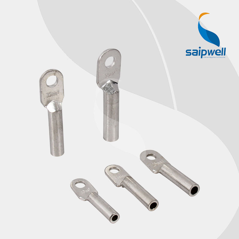
But the smaller the wire the better for crimps. Larger wires need specialised equipment and stronger harder terminals with thicker walls to securely crimp. Those can be crimped with a hydraulic crimper like you have so that it really is as secure as soldering. And oxygen is excluded because they are tight! But the cheap copper tinned/zinc plated ones are far too weak. One sharp pull and out they come. These below are cast rather than a bit of thin copper tubing.
-
Burgerman - Site Admin
- Posts: 69927
- Joined: 27 May 2008, 21:24
- Location: United Kingdom
Re: S646se - Full Pack Project - First Attempt
![]() by expresso » 10 Apr 2016, 23:54
by expresso » 10 Apr 2016, 23:54
Burgerman wrote:Not if its ok. But these things like oxidised wires that go black for eg takes time. Adding a little solder means that they stay connected and dont cause problems later. At least its only the 9 charge balance wires? And they dont get wet.
But the smaller the wire the better for crimps. Larger wires need specialised equipment and stronger harder terminals with thicker walls to securely crimp. Those can be crimped wuth a hydraulic crimper so that it really is as secure as soldering. And oxygen is excluded. But the cheap copper tinned/zinc plated ones are far too weak. These are cast rather than a bit of thin copper tubing.
the only wires i have that are crimped on there are the balance wires now - with the marine rings 3m adhesive lined heatshrink over it - they should be sealed air tight - the rest of the wires on the pack are both crimped with hydraulic crimper soldered added inside during the crimp - torched and melted inside - heat shrink over it -
i am new to this - so who knows if i managed to get that correct either - but there is was solder added and heated up after to melt inside -
the Two main wires that are connected to the big pack on the bottom - are screwed down on the 3rd row of screws on 0 and 8 - wire runs under the buss bars to Anderson for the Chair connection - thats 8 AWG thickest wire i used there -
i think you though i was talking about those two wires before ?
Quickie 636 - 230ah LifePo4
- expresso
- Posts: 11985
- Joined: 10 May 2010, 03:17
Re: S646se - Full Pack Project - First Attempt
![]() by Burgerman » 11 Apr 2016, 00:01
by Burgerman » 11 Apr 2016, 00:01
I never know exactly what wires you mean. But I was talking about the extra cells sat on top.
-
Burgerman - Site Admin
- Posts: 69927
- Joined: 27 May 2008, 21:24
- Location: United Kingdom
Re: S646se - Full Pack Project - First Attempt
![]() by expresso » 11 Apr 2016, 00:05
by expresso » 11 Apr 2016, 00:05
Burgerman wrote:I never know exactly what wires you mean. But I was talking about the extra cells sat on top.
yes thats correct - the extra cells on top - instead of having buss bars there - i am using wires to connect it - the MAIN power wires that go to the Chairs Main anderson - those are the thickest i used and those are under the buss bars to the 3rd screw down
Quickie 636 - 230ah LifePo4
- expresso
- Posts: 11985
- Joined: 10 May 2010, 03:17
Re: S646se - Full Pack Project - First Attempt
![]() by Burgerman » 11 Apr 2016, 00:12
by Burgerman » 11 Apr 2016, 00:12
Forget about those. The CELLS ON TOP need a fatter cable for the pos and neg. As I have explained above several times!
-
Burgerman - Site Admin
- Posts: 69927
- Joined: 27 May 2008, 21:24
- Location: United Kingdom
Re: S646se - Full Pack Project - First Attempt
![]() by expresso » 11 Apr 2016, 00:18
by expresso » 11 Apr 2016, 00:18
Burgerman wrote:Forget about those. The CELLS ON TOP need a fatter cable for the pos and neg. As I have explained above several times!
Ok i got that part - i though you got confused - and believed we were talking about different connections - wiring etc, -
thats going to pose a big challenge to get a fatter cable on those top cells 0 and 8 - i may not be able to do it - almost feel this isnt going to work out for the 105ah pack after all
Quickie 636 - 230ah LifePo4
- expresso
- Posts: 11985
- Joined: 10 May 2010, 03:17
Re: S646se - Full Pack Project - First Attempt
![]() by Burgerman » 11 Apr 2016, 00:26
by Burgerman » 11 Apr 2016, 00:26
But I already looked back just now at your pics and those already exist!
download/file.php?id=4839&mode=view
download/file.php?id=4839&mode=view
-
Burgerman - Site Admin
- Posts: 69927
- Joined: 27 May 2008, 21:24
- Location: United Kingdom
Re: S646se - Full Pack Project - First Attempt
![]() by expresso » 11 Apr 2016, 00:37
by expresso » 11 Apr 2016, 00:37
Burgerman wrote:But I already looked back just now at your pics and those already exist!
download/file.php?id=4839&mode=view
i was just testing that wire to see if it fitted well enough - the length etc, - i didn feel well about that wire in the pic - i removed it - that cable is 12 AWG - the same size as the PL 8 charge cable is -
which is 3.31 mm on the chart - according to you thats not thick enough for that connection ? i though it was
heres another i was testing to get the right size with the rings and length - this one is crimped and soldered - - i have another idea then - i will try it during the week - - instead of trying to connect it to the front screw -
will make a longer wire - and run it out the side past the orange tab and around to the 3 screw down or 2nd which ever is free there - - wont be pretty or neat - but i may be able to use the thicker wire there then -
and use the 14 AWG for the middle cells 2 4 6 only -
i will have to make a cable and see -
Quickie 636 - 230ah LifePo4
- expresso
- Posts: 11985
- Joined: 10 May 2010, 03:17
Re: S646se - Full Pack Project - First Attempt
![]() by expresso » 11 Apr 2016, 00:52
by expresso » 11 Apr 2016, 00:52
have to visit this place - 
Quickie 636 - 230ah LifePo4
- expresso
- Posts: 11985
- Joined: 10 May 2010, 03:17
Re: S646se - Full Pack Project - First Attempt
![]() by Burgerman » 11 Apr 2016, 01:00
by Burgerman » 11 Apr 2016, 01:00
Very funny.
Its a little small. Use something a bit heavier if possible just in case, but make it a foot long, and connect it sideways in a loop if needed... Doesent need to be short.
If you cant fit something a bit fatter then that size will work. Think of it as an addon, with thin wires to make its cells balance.
-
Burgerman - Site Admin
- Posts: 69927
- Joined: 27 May 2008, 21:24
- Location: United Kingdom
Re: S646se - Full Pack Project - First Attempt
![]() by Scollard » 11 Apr 2016, 02:28
by Scollard » 11 Apr 2016, 02:28
OK. Back from the conference.
Use the 12 AWG, if you can't make the short wire work then make a longer wire and bend it under the top pack. One of the reasons you might have trouble bending them is because of solder. If you wick solder up the wire it will not bend. 12 AWG, the proper marine terminals, crimped properly, heat shrunk is all you need and it will never corrode. Make them 6 inches long, attach one end under the top pack and then bend it around and attached to the top row of the top pack. No problem. Should bend easy. You are better off with the 12 AWG in all 5 positions. Make the wire longer. It will work out. You don't have to bend a 90˚ directly to make the connection to the top row of the top pack. Let the wire come out from under the pack and then curve if back to attach to the top. Don't worry about making the tight turn, make it gentle.
Use the 12 AWG, if you can't make the short wire work then make a longer wire and bend it under the top pack. One of the reasons you might have trouble bending them is because of solder. If you wick solder up the wire it will not bend. 12 AWG, the proper marine terminals, crimped properly, heat shrunk is all you need and it will never corrode. Make them 6 inches long, attach one end under the top pack and then bend it around and attached to the top row of the top pack. No problem. Should bend easy. You are better off with the 12 AWG in all 5 positions. Make the wire longer. It will work out. You don't have to bend a 90˚ directly to make the connection to the top row of the top pack. Let the wire come out from under the pack and then curve if back to attach to the top. Don't worry about making the tight turn, make it gentle.
- Scollard
- Posts: 258
- Joined: 29 Aug 2015, 01:43
- Location: Seattle, WA
Re: S646se - Full Pack Project - First Attempt
![]() by shirley_hkg » 11 Apr 2016, 04:01
by shirley_hkg » 11 Apr 2016, 04:01
Length of connection is also meaningful . A 3 inches long 1.5 mm wire can take 30A easily.
Your add-on will only be drawn 10 or 15 amp at peaks for very short periods of time, so 1.5 mm for the two ends is already overkilled. Thinner wires even, for the balance leads.
Meaningless to chase after big cables blindly.
Your add-on will only be drawn 10 or 15 amp at peaks for very short periods of time, so 1.5 mm for the two ends is already overkilled. Thinner wires even, for the balance leads.
Meaningless to chase after big cables blindly.
- shirley_hkg
- Posts: 4483
- Joined: 31 Dec 2010, 13:42
Re: S646se - Full Pack Project - First Attempt
![]() by Burgerman » 11 Apr 2016, 05:45
by Burgerman » 11 Apr 2016, 05:45
Length of connection is also meaningful . A 3 inches long 1.5 mm wire can take 30A easily.
Your add-on will only be drawn 10 or 15 amp at peaks for very short periods of time, so 1.5 mm for the two ends is already overkilled. Thinner wires even, for the balance leads.
Meaningless to chase after big cables blindly.
https://www.bluesea.com/files/resources ... hartlg.jpg
Is it? Invacare are already in the "hotseat" for undersized wiring fires. At very least, he should use 10, and better, 8 gauge for "belt and braces" according to most charts. And remember that the DIY crimp is worse than the wire.
With an Rnet 120A per motor controller, its possible accelerating up a ramp for eg, to draw 240A peak. Div by 7 = 34 Amps via the two END wires on that top part. Or 30A from a 100Amp controller. I dont consider thin 14 or 16 gauge cables adequate. And thats in the event that the current is drawn from all cells equally. And even without a bad or oxidised crimp in a years time.
For a second or two after which the insulation melts off it. I charge 30A on 10 mm sq cabes and they get pretty warm. And thats 7x bigger...A 3 inches long 1.5 mm wire can take 30A easily.
I prefer to build things that are over engineered and belt and braces, so we have no fires or reliability issues. Likewise a crimp done on a cheap soft ring terminal no matter how pretty will oxydise over time, And possibly heat up and oxydise more, and is physically just weak. When you are sat on the thing, I would be concerned about safety. Especially if it wasnt myself and aware of what can happen.
But of course almost anything will work.
-
Burgerman - Site Admin
- Posts: 69927
- Joined: 27 May 2008, 21:24
- Location: United Kingdom
Re: S646se - Full Pack Project - First Attempt
![]() by LROBBINS » 11 Apr 2016, 08:38
by LROBBINS » 11 Apr 2016, 08:38
- i can drop a solder on the end after i crimp it on uninsulated rings -
You can't just "drop" solder on the end - the terminal must be heated hot enough to make the solder flow, then touch the solder to the hot metal. If it doesn't flow like water, it isn't making a connection. Only a tiny bit of solder is needed; just enough to ensure contact between the wire and the barrel and absolutely not so much that it flows back into the wire.
You CAN do this on insulated terminals without damaging the insulation. Hold the iron to the terminal a tiny distance from the end of the barrel, touch the solder to the end of the wire, as soon as it flows move the iron away.
Ciao,
Lenny
- LROBBINS
- Posts: 5774
- Joined: 27 Aug 2010, 09:36
- Location: Siena, Italy
Re: S646se - Full Pack Project - First Attempt
![]() by expresso » 11 Apr 2016, 16:01
by expresso » 11 Apr 2016, 16:01
Ok - i got to think some during sleep which is hard to do now since this is all i am thinking about - i agree with everyone here -
LRobbins - if i did solder the ends - i would heat it up first add a touch of flux on the wire end first - crimp - heat it and touch the solder - when i said drop a little on the end - thats what i meant - but didn't sound that way - my mistake not explaining that -
BM - i agree with you also - be safe and over do it if you can with the wire size to be sure - -
Scollard - SO GLAD your back i am driving myself crazy here trying to get it right - what you said is what i though about last night - i was focused on making it neat and nice - short wire etc, and didnt think of other ways which is excatly how i will do it now - and i am going to use 8 AWG wire for 0 and 8 - i will make a longer cable and let it bend naturally -
the way i tested it - it will go around the side on the 0 to the rear screw but it wont be underneath it - bend out the side and back in - that i can do - - now the 3 inner cells 2 4 6 - i was going to now use the 14 awg wire for that -
would make it easier to bend around and attach - - you suggest i try again with the 12 AWG wire for those numbers also ? or can i get away with using the 14 AWG there - numbers 1 3 5 7 - have 12 awg wires -
LRobbins - if i did solder the ends - i would heat it up first add a touch of flux on the wire end first - crimp - heat it and touch the solder - when i said drop a little on the end - thats what i meant - but didn't sound that way - my mistake not explaining that -
BM - i agree with you also - be safe and over do it if you can with the wire size to be sure - -
Scollard - SO GLAD your back
the way i tested it - it will go around the side on the 0 to the rear screw but it wont be underneath it - bend out the side and back in - that i can do - - now the 3 inner cells 2 4 6 - i was going to now use the 14 awg wire for that -
would make it easier to bend around and attach - - you suggest i try again with the 12 AWG wire for those numbers also ? or can i get away with using the 14 AWG there - numbers 1 3 5 7 - have 12 awg wires -
Quickie 636 - 230ah LifePo4
- expresso
- Posts: 11985
- Joined: 10 May 2010, 03:17
Re: S646se - Full Pack Project - First Attempt
![]() by Burgerman » 11 Apr 2016, 17:06
by Burgerman » 11 Apr 2016, 17:06
and i am going to use 8 AWG wire for 0 and 8
10 will do. Silicone like the PL8 charge cables, is used because its very flexible, and because it doesent melt when it gets quite hot charging at 40A... So that type of cable may make it easier.
12 or 14 will do for balance wires. But 12 physically more robust.
-
Burgerman - Site Admin
- Posts: 69927
- Joined: 27 May 2008, 21:24
- Location: United Kingdom
Re: S646se - Full Pack Project - First Attempt
![]() by expresso » 11 Apr 2016, 18:03
by expresso » 11 Apr 2016, 18:03
Burgerman wrote:and i am going to use 8 AWG wire for 0 and 8
10 will do. Silicone like the PL8 charge cables, is used because its very flexible, and because it doesent melt when it gets quite hot charging at 40A... So that type of cable may make it easier.
12 or 14 will do for balance wires. But 12 physically more robust.
Ok - when you say balance wires - you mean 2 4 6 Cells ?
i didnt know they are considered the balance cells - i think i get that now - i didnt know - the two ends are the main power and get charged up and used heavy - all the numbers are considered the balance wires - Cells etc,
2 4 6 , 1 3 5 7 - all balance
i am going to make the 12 awg work if i can - and 8 awg for the O and 8 - i have the wire - will try my best - once i take a short break a rest for a day or two - to get it together again
i purchase 14 awg thinking i was going to use that - but its ok - i may have too to use if i cant get the 12 awg - but will try 12 first to match it to the 1 3 5 7 which have 12 awg -
will make it longer the cable and just let it be how ever it bends naturally if i can - i think what Scollard said 6 inches may be good -
thanks - heading out today -
Quickie 636 - 230ah LifePo4
- expresso
- Posts: 11985
- Joined: 10 May 2010, 03:17
Re: S646se - Full Pack Project - First Attempt
![]() by Burgerman » 11 Apr 2016, 18:45
by Burgerman » 11 Apr 2016, 18:45
Yes. I said that the day before (12 inches) but you dont read
Your AddOn pack has 2 wires to charge and discharge. Its where all the power goes in and out.
Your extra cells that sit on top is exactly the same as your addon...
All the power comes from the ends of the battery. 8 and 0 -- The 26V. The plus/minus.
No power in use - apart from that required to keep all the cells in balance when you charge - goes across all the middle cells. 2, 4, 6, and 1, 3, 5, 7 only have about 1A of balance current worst case as you charge.
Ok - when you say balance wires - you mean 2 4 6 Cells ?
i didnt know they are considered the balance cells - i think i get that now - i didnt know - the two ends are the main power and get charged up and used heavy - all the numbers are considered the balance wires - Cells etc,
2 4 6 , 1 3 5 7 - all balance
Your AddOn pack has 2 wires to charge and discharge. Its where all the power goes in and out.
Your extra cells that sit on top is exactly the same as your addon...
All the power comes from the ends of the battery. 8 and 0 -- The 26V. The plus/minus.
No power in use - apart from that required to keep all the cells in balance when you charge - goes across all the middle cells. 2, 4, 6, and 1, 3, 5, 7 only have about 1A of balance current worst case as you charge.
-
Burgerman - Site Admin
- Posts: 69927
- Joined: 27 May 2008, 21:24
- Location: United Kingdom
Re: S646se - Full Pack Project - First Attempt
![]() by Scollard » 11 Apr 2016, 19:51
by Scollard » 11 Apr 2016, 19:51
No. No. Np. The top pack is not like an add-on. It is a 7th row. You should use the 12 AWG wires to attack all 0,1,2,3,4,5,6,7,8. You do not need bigger wires for positions 0 and 8. You want 12 AWG to wire in the top pack so when it comes time to balance there is minimal resistance accessing the 7th row cells. It's not going to be a good as having a busbar but it will be pretty close.
You can use the larger gauge wire when making the cable that will plug into the chair.
Everyone is making it too complicated. It's not. The 12 AWG wires take the place of the busbars. Stop referring to them as balance wires. The are flexible busbars to attach a 7th row. You still wire up the larger bottom part like normal. You have 9 balance wires, 2 charge wires, 2 wires to attach to the chair. None of these wires have anything to do with the 7th row sitting on top.
- Scollard
- Posts: 258
- Joined: 29 Aug 2015, 01:43
- Location: Seattle, WA
Re: S646se - Full Pack Project - First Attempt
![]() by expresso » 11 Apr 2016, 23:21
by expresso » 11 Apr 2016, 23:21
Ok then - i was getting confused with the term of balance wires etc, -
the balance wires are already attached to the bottom pack -
the MAIN power to the Pack is already attached also - which goes to the MAIN Chair power - Anderson - those wires are 8 AWG -
the only wires i have left to attach are the Charge wires - i will use XT90 connector for that with 12 AWG wire also - same as the PL 8 charge wires -
that leaves me just the 7th row - which i will proceed with using 12 AWG in place of the buss bars - thats correct the 12 AWG is taking the place of the buss bars
this in the end is a 8x7 pack -105ah - if i can make it work - i guess i will return the 14 Awg wire i ordered - or just keep it maybe i may need one day -
so its settled then - i can continue now - hopefully get this done with in a week or two -
Quickie 636 - 230ah LifePo4
- expresso
- Posts: 11985
- Joined: 10 May 2010, 03:17
Return to Everything Powerchair
Who is online
Users browsing this forum: Kande_ian, Pierro, tettralytic and 142 guests